
Related Manuals for Whirlpool DryAire LMA1053L


Summary of Contents for Whirlpool DryAire LMA1053L
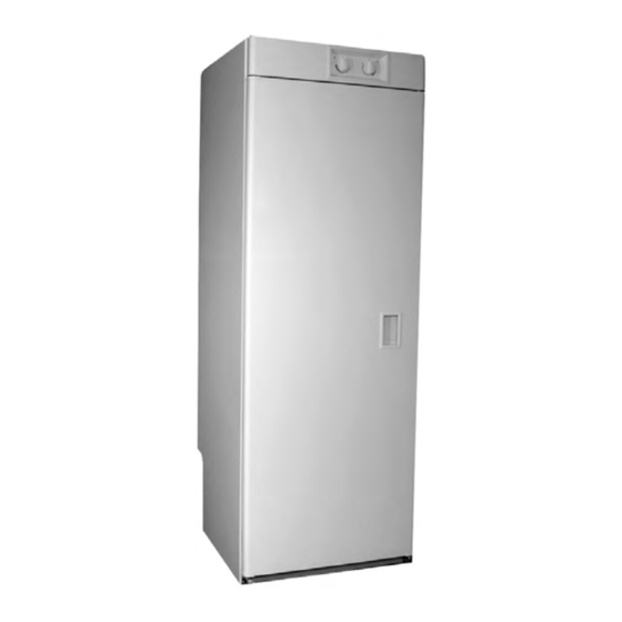
- Page 1 CONSUMER SERVICES TECHNICAL L-72 EDUCATION GROUP PRESENTS DryAire DRYING CABINET Model LMA1053L JOB AID Part No. 8178202...
- Page 2 • Successfully perform necessary repairs. • Successfully return the Drying Cabinet to its proper operational status. WHIRLPOOL CORPORATION assumes no responsibility for any repairs made on our products by anyone other than Authorized Service Technicians. Copyright © 2002, Whirlpool Corporation, Benton Harbor, MI 49022...
-
Page 3: Table Of Contents
Model & Serial Number Designations ..................... 1-2 Model & Serial Number Label & Wiring Diagram Locations ............1-3 Specifications ..........................1-4 Whirlpool DryAire Drying Cabinet Warranty ................... 1-5 INSTALLATION INFORMATION ......................2-1 Mounting The Cabinet ........................2-1 Changing The Door Swing ......................2-2 PRODUCT OPERATION ........................ - Page 4 — NOTES — - iv -...
-
Page 5: General
GENERAL SAFETY FIRST Your safety and the safety of others is very important. We have provided many important safety messages in this Job Aid and on the appliance. Always read and obey all safety messages. This is the safety alert symbol. This symbol alerts you to hazards that can kill or hurt you and others. -
Page 6: Model & Serial Number Designations
MODEL & SERIAL NUMBER DESIGNATIONS MODEL NUMBER MODEL NUMBER L Q 0 INTERNATIONAL SALES IND. OR MARKETING CHANNEL IF PRESENT PRODUCT GROUP: L = DOMESTIC LAUNDRY PRODUCT IDENTIFICATION: M = DRYING CABINET FEATURE CODE 1: A = BUILT-IN VERSION FEATURE CODE 2: FIRST DIGIT 1 = CYCLES 1 THROUGH 9 SECOND DIGIT... -
Page 7: Model & Serial Number Label & Wiring Diagram Locations
MODEL & SERIAL NUMBER LABEL & WIRING DIAGRAM LOCATIONS Wiring Diagram Model & Serial Number Label... -
Page 8: Specifications
SPECIFICATIONS Model No. LMA1053LQ, T Color Q = White, T = Biscuit Dimensions/Weight: Overall Height 170.8 cm (67-1/4″) Cabinet Width 59.5 cm (23-1/2″) Cabinet Depth 61 cm (24″) Capacity (dry load) 3.5 kg (7.7 lbs.) Weight 56 kg (123 lbs.) Cycle Configuration: Temperature Room Temperature to 65.6°C (150°F) -
Page 9: Whirlpool Dryaire Drying Cabinet Warranty
Whirlpool dealer. If you need service, help can be found by checking the “Assistance Or Service” section of the Use and Care Guide, or by calling the Whirlpool Customer Interaction Center telephone number, 1-800-253-1301, from anywhere in the U.S.A. - Page 10 — NOTES —...
-
Page 11: Installation Information
INSTALLATION INFORMATION Install the plastic plugs provided with the MOUNTING THE CABINET unit and place them into the leveling leg NOTE: This drying cabinet is intended to be holes. vented into the room. Do not vent it into a Secure the top of the cabinet to the wall chimney, wall, or ceiling exhaust duct. -
Page 12: Changing The Door Swing
CHANGING THE DOOR SWING Upper Pivot Pin To reverse the way the cabinet door swings open and closed, perform the following steps. Close the cabinet door. Pry the plastic hole plugs from the cabinet. Use a screwdriver and remove the lower pivot pin from the door hinge. -
Page 13: Product Operation
PRODUCT OPERATION When hanging clothing to dry, keep the longer DRYING CLOTHES articles, such as pants and dresses, toward the The dryer contains three racks with hanger dryer walls of the cabinet, and shorter articles, bars. The racks can be pulled out on rails to such as shirts and sweaters, toward the middle. -
Page 14: Controls & Switches
Heating Control PTS Switch Timer Control CONTROLS & SWITCHES The control panel has two controls and two switches, which perform the following func- tions: Heating Control—controls the temperature of the air circulating inside the cabinet. The con- trol ranges are from “air only,” (the “0” position), to normal drying, to “fast drying.”... -
Page 15: Component Access
COMPONENT ACCESS COMPONENT LOCATIONS The components that are serviced in this section of the Job Aid are shown below. Blower Assembly Heater Temperature Sensor High Limit Thermostat Thermostat Timer Component Panel Push-To-Start Switch Inside Of Component Panel Relay Door Switch Terminal Block... -
Page 16: Removing The Component Panel
REMOVING THE COMPONENT PANEL Remove the mounting screw from the WARNING bottom of the component panel. Electrical Shock Hazard Disconnect power before servicing. Replace all parts and panels before operating. Failure to do so can result in death or Component Panel Screw electrical shock. -
Page 17: Removing The High Limit Thermostat And The Heater
REMOVING THE HIGH LIMIT THERMOSTAT AND THE HEATER To remove the heater: WARNING a) Remove the two Torx screws from the high limit thermostat. b) Disconnect the three wires from the heater terminals. High Limit Thermostat Electrical Shock Hazard Heater Disconnect power before servicing. -
Page 18: Removing The Timer
REMOVING THE TIMER Remove the two screws and lockwashers WARNING from the timer. Timer Screws/ Lockwashers Electrical Shock Hazard Disconnect power before servicing. Replace all parts and panels before operating. Failure to do so can result in death or Disconnect the wires from the thermostat electrical shock. -
Page 19: Removing The Blower Assembly, The Thermostat & Temperature Sensor
REMOVING THE BLOWER ASSEMBLY, THE THERMOSTAT & TEMPERATURE SENSOR b) Remove the knob from the thermostat WARNING control shaft. Thermostat Knob Electrical Shock Hazard Disconnect power before servicing. Replace all parts and panels before operating. c) Remove the two screws and lock- Failure to do so can result in death or washers from the thermostat. -
Page 20: Removing The Relay
REMOVING THE RELAY Push down on the top of the relay case and WARNING rotate the lower rear up to unclip the relay from the front panel. Push Down On Front Of Relay Case Electrical Shock Hazard Disconnect power before servicing. Replace all parts and panels before operating. -
Page 21: Removing The Push-To-Start & Door Switches
REMOVING THE PUSH-TO-START & DOOR SWITCHES To remove the push-to-start (PTS) WARNING switch or the door switch: a) Disconnect the wires from the termi- nals. b) Press in on the locking arms and push the switch out of the front panel cutout. PTS Switch Electrical Shock Hazard Disconnect power before servicing. -
Page 22: Removing The Component Panel-Mounted Terminal Block
REMOVING THE COMPONENT PANEL-MOUNTED TERMINAL BLOCK Loosen the 3 wire screws and pull the WARNING wires out of the component panel-mounted terminal block. Remove the two screws from the compo- nent panel-mounted terminal block, and remove the block from its mounting bracket. Electrical Shock Hazard Ground Wire Disconnect power before servicing. -
Page 23: Removing The Power Cord And Cabinet-Mounted Terminal Block
REMOVING THE POWER CORD AND CABINET-MOUNTED TERMINAL BLOCK WARNING Electrical Shock Hazard Disconnect power before servicing. Replace all parts and panels before operating. Power Cord Strain Relief Clamp Screws Failure to do so can result in death or electrical shock. NOTE: Sharp edges may be present. -
Page 24: Removing The Cabinet Door
REMOVING THE CABINET DOOR With the cabinet door closed, remove the WARNING two screws from the top pivot bracket and remove the bracket. Electrical Shock Hazard Disconnect power before servicing. Replace all parts and panels before Top Pivot Bracket operating. &... -
Page 25: Component Testing
COMPONENT TESTING Before testing any of the components, perform • Check all connections before replacing com- the following checks: ponents, looking for broken or loose wires, failed terminals, or wires not pressed into • The most common cause for control failure is connectors far enough. -
Page 26: Fan Motor
WARNING Electrical Shock Hazard Disconnect power before servicing. Replace all parts and panels before operating. Failure to do so can result in death or electrical shock. FAN MOTOR THERMOSTAT Fan Motor Terminals Thermostat Terminals Refer to page 4-5 for the procedure for servic- ing the blower assembly. -
Page 27: Timer
WARNING Electrical Shock Hazard Disconnect power before servicing. Replace all parts and panels before operating. Failure to do so can result in death or electrical shock. TIMER DOOR & PUSH-TO-START (PTS) a0 / a1 b0 / b1 SWITCHES Terminals Terminals A Terminal B Terminal PTS Switch... - Page 28 — NOTES —...
-
Page 29: Wiring Diagram
WIRING DIAGRAM Timer Timer Motor Door Switch Relay Push-To-Start Switch Relay Coil Motor High Limit 600W Thermostat Thermostat Heater Element 24 kΩ 600W NOTE: indicates wire number. - Page 30 — NOTES —...
- Page 31 PRODUCT SPECIFICATIONS WARRANTY INFORMATION SOURCES IN THE UNITED STATES: FOR PRODUCT SPECIFICATIONS AND WARRANTY INFORMATION CALL: FOR WHIRLPOOL PRODUCTS: 1-800-253-1301 FOR KITCHENAID PRODUCTS: 1-800-422-1230 FOR ROPER PRODUCTS: 1-800-447-6737 FOR TECHNICAL ASSISTANCE WHILE AT THE CUSTOMER’S HOME CALL: THE TECHNICAL ASSISTANCE LINE: 1-800-253-2870...
- Page 32 CORPORATION...
Need help?
Do you have a question about the DryAire LMA1053L and is the answer not in the manual?
Questions and answers