Table of Contents

Subscribe to Our Youtube Channel
Related Manuals for Chamberlain LM-1600


Summary of Contents for Chamberlain LM-1600
- Page 1 Central Motor Installation Manual Models LM-1600, LM-2000, LM-2800, LM-3600, LM-1600HV, LM-2000HV, LM-2800HV, LM-3600HV LiftMaster 845 Larch Avenue Elmhurst, Illinois 60126-1196 LiftMaster.com...
-
Page 2: Table Of Contents
Table of Contents Warnings ............2 Application ............ 3 Motor Selection ..........3 Specifi cations ..........4 Tools ............4 Overview ............5 Installation ..........6-8 WARNING Adjustment/Operation ........9 Maintenance ..........9 Warranty ............9 Repair Parts ..........10 Contact Us ...........10 WARNING Warnings IMPORTANT INSTALLATION INSTRUCTIONS... -
Page 3: Application
270 lbs. 122 kg Motor should be rated for 120% of door weight 324 lbs. 147 kg Choose Next Largest Capacity Motor All Lift Capacities are at the Rated Load LM-1600 330 lbs. 150 kg LM-1600HV 330 lbs. 150 kg LM-2000 396 lbs. -
Page 4: Specifi Cations
Specifi cations Model Number LM-1600/LM-1600HV LM-2000/LM-2000HV LM-2800/LM-2800HV LM-3600/LM-3600HV Power Supply 120 Vac - 50/60Hz (LM-1600) 120 Vac - 50/60Hz (LM-2000) 120 Vac - 50/60Hz (LM-2800) 120 Vac - 50/60Hz (LM-3600) Voltage/Hz 230 Vac - 50/60Hz (LM-1600HV) 230 Vac - 50/60Hz (LM-2000HV) -
Page 5: Overview
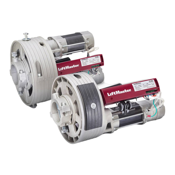
Overview The Central Motor consists of an electric motor secured to the dead shaft of the door with a clamping mechanism. The motor has a gear attached to the front of the armature. The gear drives the inside teeth of a circular crown and that rotates around the front of the motor and the dead shaft. The motor stays fi... -
Page 6: Installation
Installation Install the Motor To prevent possible SERIOUS INJURY or DEATH: • DO NOT connect electric power until instructed to do so. • Disable ALL locks and remove ALL ropes connected to door BEFORE installing and operating door operator to avoid entanglement. 1. - Page 7 Installation Attach Brake to the Control Station (Key Lock Box) WARNING WARNING To prevent possible SERIOUS INJURY or DEATH from a closing door: • The constant-pressure-to-close switch MUST be installed within sight of the door, out of reach of children, at a minimum height of 4.92' (1.5 m) and away from ALL moving parts of the door.
- Page 8 Installation Attach Wire Connectors to Wires 1. Remove the screws (4) securing the switch plate to the lock box housing. 2. Slide the plastic boot on to the wire. 3. Strip 1/2" (12.7 mm) of insulation from the end of the wire. 4.
-
Page 9: Adjustment/Operation
LiftMaster warrants these products to be free from defects in material and workmanship for a period of two (2) years beginning with the placement of the order. In the event that you should have a problem with a LiftMaster Central Motor or Accessory, contact americalatina@chamberlain.com. -
Page 10: Repair Parts
Motor for Model LM2000 230 Vac EM28-120 Motor for Model LM2800 120 Vac EM28-230 Motor for Model LM2800 230 Vac EM36-120 Motor for Model LM3600 120 Vac EM36-230 Motor for Model LM3600 230 Vac Contact Us For support contact: americalatina@chamberlain.com... - Page 11 Motor Central Manual de instalación Modelos LM-1600, LM-2000, LM-2800, LM-3600, LM-1600HV, LM-2000HV, LM-2800HV, LM-3600HV LiftMaster 845 Larch Avenue Elmhurst, Illinois 60126-1196 LiftMaster.com...
- Page 12 Índice Advertencias ..........12 Aplicación ............13 Elección del motor ..........13 Especifi caciones técnicas .........14 Herramientas necesarias ........14 Descripción general ........15 Instalación ..........16-18 Regulación/Operación ........19 Mantenimiento ..........19 Garantía ............19 Repuestos ............20 Comuníquese con nosotros .......20 Advertencias INSTRUCCIONES IMPORTANTES DE INSTALACIÓN ADVERTENCIA Para reducir el riesgo de LESIONES GRAVES o la MUERTE: 1.
- Page 13 El motor debe tener una capacidad del 120% del peso de la puerta 324 lbs. 147 kg Elegir la potencia inmediatamente superior Todas las capacidades de elevación se encuentran en la carga nominal LM-1600 330 lbs. 150 kg LM-1600HV 330 lbs.
- Page 14 Número de modelo LM-1600/LM-1600HV LM-2000/LM-2000HV LM-2800/LM-2800HV LM-3600/LM-3600HV Voltaje y frecuencia 120 Vac - 50/60Hz (LM-1600) 120 Vac - 50/60Hz (LM-2000) 120 Vac - 50/60Hz (LM-2800) 120 Vac - 50/60Hz (LM-3600) de alimentación 230 Vac - 50/60Hz (LM-1600HV) 230 Vac - 50/60Hz (LM-2000HV)
- Page 15 Descripción general El motor central es un motor eléctrico acoplado al eje fi jo de la puerta. El motor tiene un engranaje acoplado al frente de la armadura. El engranaje conduce los dientes interiores de una corona circular que gira sobre el eje fi jo. El motor permanece fi...
- Page 16 Instalación Instalación del motor ADVERTENCIA Para evitar una LESIÓN GRAVE O INCLUSO LA MUERTE: • NO conecte la energía eléctrica hasta que se le indique. • Quitar TODOS los seguros y retirar TODAS las cuerdas conectadas a la puerta ANTES de instalar y hacer funcionar el operador, para evitar que se enreden.
- Page 17 Instalación Conectar el freno a la estación de control (caja con cerradura) ADVERTENCIA Para evitar la posibilidad de una LESIÓN GRAVE O INCLUSO LA MUERTE cuando la puerta del garaje se esté cerrando: • El relé de presión constante de cierre DEBE instalarse a la vista desde la puerta, fuera del alcance de los niños, a una altura mínima de 1,5 metros y alejado de TODAS las partes móviles de la puerta.
- Page 18 Instalación Conectar los conectores a los conductores 1. Quitar los cuatro tornillos que fi jan la tapa de la llave al alojamiento. 2. Deslizar el manguito plástico en el conductor. 3. Quitar 12.7 mm (1/2 de pulg.) de aislamiento del extremo del conductor. 4.
- Page 19 Regulación/Operación Regulación de límites de carrera 1. Retirar toda abrazadera o perno que retenga la puerta en posición cerrada. Verifi car que la puerta esté en posición cerrada normal, sin pandeo. Tapa de límites 2. Quitar la tapa de la caja de límites de carrera. de carrera 3.
- Page 20 Motor para el Modelo LM2800 230 VCA EM36-120 Motor para el Modelo LM3600 120 VCA EM36-230 Motor para el Modelo LM3600 230 VCA Comuníquese con nosotros Apoyo técnico: americalatina@chamberlain.com ® LiftMaster All Rights Reserved 01-37396 Reservados todos los derechos de ley.
Need help?
Do you have a question about the LM-1600 and is the answer not in the manual?
Questions and answers