Table of Contents
Advertisement
Quick Links
MODEL T32540
DUAL-SPINDLE DOWELING JOINTER
OWNER'S MANUAL
(For models manufactured since 10/20)
COPYRIGHT © DECEMBER, 2020 BY GRIZZLY INDUSTRIAL, INC.
WARNING: NO PORTION OF THIS MANUAL MAY BE REPRODUCED IN ANY SHAPE
OR FORM WITHOUT THE WRITTEN APPROVAL OF GRIZZLY INDUSTRIAL, INC.
#KS21481 PRINTED IN CHINA
V1.12.20
Advertisement
Table of Contents

Related Manuals for Grizzly T32540


Summary of Contents for Grizzly T32540
- Page 1 (For models manufactured since 10/20) COPYRIGHT © DECEMBER, 2020 BY GRIZZLY INDUSTRIAL, INC. WARNING: NO PORTION OF THIS MANUAL MAY BE REPRODUCED IN ANY SHAPE OR FORM WITHOUT THE WRITTEN APPROVAL OF GRIZZLY INDUSTRIAL, INC. #KS21481 PRINTED IN CHINA V1.12.20...
- Page 2 This manual provides critical safety instructions on the proper setup, operation, maintenance, and service of this machine/tool. Save this document, refer to it often, and use it to instruct other operators. Failure to read, understand and follow the instructions in this manual may result in fire or serious personal injury—including amputation, electrocution, or death.
-
Page 3: Table Of Contents
Table of Contents SECTION 1: SAFETY .......................2 Safety Instructions for Power Tools ................2 Additional Safety for Doweling Jointers ..............4 SECTION 2: INTRODUCTION ..................5 Manual Accuracy ......................5 Contact Info ........................5 Machine Data Sheet ....................6 Identification ........................7 Controls & Components .....................8 SECTION 3: POWER SUPPLY ..................9 SECTION 4: SETUP .......................11 Unpacking .........................11 Inventory ........................12... -
Page 4: Section 1: Safety
Operating tools in when operating or observing machinery to these areas greatly increases risk of acci- reduce the risk of eye injury or blindness dents and injury. from flying particles. Everyday eyeglasses are not approved safety glasses. Model T32540 (Mfd. Since 10/20) - Page 5 FORCING TOOLS.. Use right tool for job, forming the intended operation, stop and do not force it. It will do job safer and using the machine! Contact our Technical better at rate for which it was designed. Support at (570) 546-9663. Model T32540 (Mfd. Since 10/20)
-
Page 6: Additional Safety For Doweling Jointers
Failure to do so could result operator injury. If normal safety pre- in serious personal injury, damage cautions are overlooked or ignored, to equipment or poor work results. serious personal injury may occur. Model T32540 (Mfd. Since 10/20) -
Page 7: Section 2: Introduction
For your convenience, we post all avail- able documentation on our website at www.grizzly.com. Any updates to this Grizzly Documentation Manager P.O. Box 2069 document will be reflected on our website Bellingham, WA 98227-2069 as soon as complete. Email: manuals@grizzly.com Model T32540 (Mfd. Since 10/20) -
Page 8: Machine Data Sheet
Removable Fence with Drilling-Height Adjustment of 3/8" – 1-11/16" Drilling Angle of 0º – 90° with Stops at 22�5º, 45º, and 67�5º Dust Extraction Below Drill Bits Accessories: (2) 8mm Drill Bits Hex Wrench 2�5mm Model T32540 (Mfd. Since 10/20) -
Page 9: Identification
Fence Height Lock Knob Main Handle Fence Height Sliding Pointer Base Tool Face Drill Bit Holder Dust Port (1 of 2) To reduce your risk of serious injury, read this entire manual BEFORE using tool. Model T32540 (Mfd. Since 10/20) -
Page 10: Controls & Components
F. ON/OFF Switch: Starts and stops motor. Tool will remain running while switch is in ON position. Figure 2. Fence height, jig teeth, and jig bar components. Figure 1. Fence angle, drilling depth, and power controls. Model T32540 (Mfd. Since 10/20) -
Page 11: Section 3: Power Supply
Model T32540 (Mfd. Since 10/20) - Page 12 Below is a list of minimum gauge sizes Figure 3. Typical 1-15 plug and needed for running this tool at different receptacle. lengths: 25 Feet .......... 16AWG 50 Feet .......... 14AWG 100 Feet ........12AWG Over 100 Feet ... Not Recommended Model T32540 (Mfd. Since 10/20)
-
Page 13: Section 4: Setup
This tool presents serious injury the tool and have resolved any issues hazards to untrained users. Read between Grizzly or the shipping agent. You through this entire manual MUST have the original packaging to file a become familiar with the controls freight claim. -
Page 14: Inventory
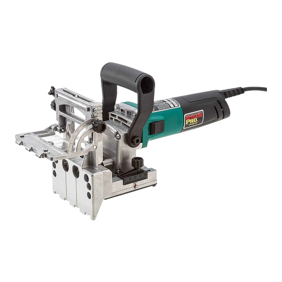
If you cannot find an item on this Figure 4. Model T32540 Doweling Jointer. list, carefully check around/inside the tool and packaging materials. Often, these items get lost in pack- aging materials while unpacking or they are pre-installed at the factory. -
Page 15: Dust Collection
To connect to dust collection system: 1. Attach hose from dust collection sys- tem to dust port (see Figure 6) and The Model T32540 is equipped with a 1¼" secure with a hose clamp. dust port that can attach to a dust collec- tion system or shop vacuum. -
Page 16: Test Run
1. Clear away all setup/adjustment tools. Before installing attachments and using 2. Connect tool to power supply. your Model T32540, test run the tool to make sure it runs properly. 3. While firmly holding auxiliary handle (see Figure 7) in one hand, move... -
Page 17: Section 5: Operations
SECTION 5: OPERATIONS Installing Drill Bits To reduce your risk of serious injury, read The Model T32540 will support 6–12mm this entire manual ⁄ "– ⁄ ") drill bits. BEFORE using tool. To install drill bits: 1. DISCONNECT TOOL FROM POWER! -
Page 18: Calibrating Depth
3. Position tool against a flat piece of scrap wood (see Figure 10), and push tool body forward until cutting point of drill bits stop against wood. Hold this position. Figure 10. Positioning tool against flat wood surface. Model T32540 (Mfd. Since 10/20) -
Page 19: Adjusting Fence Angle
4. Tighten depth gauge lock knob and verify fence is secure. verify depth gauge is secure. Note: ALWAYS verify fence is secure before operating. Note: Fence angle scale is an approxi- mate value. Use additional measuring tools for precision measurements. Model T32540 (Mfd. Since 10/20) -
Page 20: Adjusting Drilling Height
Adjusting Drilling Aligning Viewer Height The Model T32540 features a clear plastic viewing screen over the drilling area to The fence uses a rack-and-pinion adjust- support accurate alignment during drilling ment mechanism that allows for drilling operations and help protect the operator at a height of ⁄... -
Page 21: Workpiece Preparation
(see Figure 17). Layout Line Registration Mark Figure 17. Layout lines and registration marks on pair of boards to be joined. Model T32540 (Mfd. Since 10/20) -
Page 22: Positioning Tool
Positioning Tool Drilling Doweling Holes The doweling jointer should always be positioned perpendicular to the workpiece The Model T32540 is capable of drilling in order to accurately drill joining surfaces holes for ⁄ "– ⁄ " dowels. (see Figure 19). -
Page 23: Gluing Dowels
4. Once drill bits reach full depth, slide jointer body backward, allowing bits to retract into base. The Model T32540 is equipped with jig 5. Turn doweling jointer OFF and wait teeth and a jig bar to enable fast and... -
Page 24: Section 6: Accessories
Replacement drill bit sets for the Model T32540 Dual-Spindle Doweling Jointer. T32544—Dust Collection Adaptor Compatible 1"–1 ⁄ " dust collection adaptor for connecting the Model T32540 to a dust collection system or shop vacuum. Figure 24. Assorted dowel pins. www.grizzly.com 1-800-523-4777 order online at or call Model T32540 (Mfd. -
Page 25: Section 7: Maintenance
If dry cleaning is insufficient, Figure 27. Location of return spring on a mild detergent on a damp cloth is recom- sliding base. mended. Keep dripping or running water away from tool at all times. Model T32540 (Mfd. Since 10/20) -
Page 26: Replacing Brushes
(see Figure 28), and gently pull handle away from tool. Note: Make sure not to pull on or dam- age the wires located in main handle during disassembly. Figure 28. Location of main handle screw. Model T32540 (Mfd. Since 10/20) -
Page 27: Section 8: Service
5. Motor bearings at fault. 5. Test by rotating shaft; rota- tional grinding/loose shaft requires bearing replace- ment. 1. Remove/replace (Page 15). Drill bits are burning 1. Drill bits dull or at fault/ workpiece. loose. Model T32540 (Mfd. Since 10/20) -
Page 28: Section 9: Parts
Please Note: We do our best to stock replacement parts whenever possible, but we cannot guarantee that all parts shown here are available for purchase. Call (800) 523-4777 or visit our online parts store at www.grizzly.com to check for availability. Main... - Page 29 PT32540085 COMPRESSION SPRING 0.5 X 10 X 6 PT32540044 DRILL BIT HOLDER PT32540086 POWER CORD 18G 3W 79" 1-15P PT32540045 GEARBOX COVER BUY PARTS ONLINE AT GRIZZLY.COM! Model T32540 (Mfd. Since 10/20) Scan QR code to visit our Parts Store.
-
Page 30: Labels & Cosmetics
Safety labels help reduce the risk of serious injury caused by machine hazards. If any label comes off or becomes unreadable, the owner of this machine MUST replace it in the original location before resuming operations. For replacements, contact (800) 523-4777 or www.grizzly.com. BUY PARTS ONLINE AT GRIZZLY.COM! Model T32540 (Mfd. -
Page 31: Warranty & Returns
WARRANTY & RETURNS Grizzly Industrial, Inc. warrants every product it sells for a period of 1 year to the original purchaser from the date of purchase. This warranty does not apply to defects due directly or indirectly to misuse, abuse, negligence, accidents, repairs or alterations or lack of maintenance.
Need help?
Do you have a question about the T32540 and is the answer not in the manual?
Questions and answers