
Related Manuals for Riello RLS 1000/M MX


Summary of Contents for Riello RLS 1000/M MX
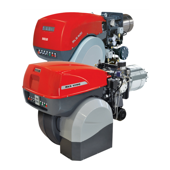
- Page 1 Installation, use and maintenance instructions Dual fuel light oil/gas burners Progressive two-stage or modulating operation CODE MODEL TYPE 20147815 RLS 1000/M MX 1311 T 20147814 RLS 1200/M MX 1312 T 20148180 (2) - 11/2020...
- Page 2 Translation of the original instructions...
-
Page 3: Table Of Contents
Contents Declarations....................................3 Information and general warnings............................4 Information about the instruction manual ........................4 Guarantee and responsibility............................5 Safety and prevention................................6 Introduction.................................. 6 Personnel training ............................... 6 Technical description of the burner ............................7 Burner designation ..............................7 Models available................................ - Page 4 Contents Servomotor adjustment ..............................31 Combustion air adjustment ............................31 6.10 Burner adjustment and output modulation .........................32 6.11 Air / fuel adjustment ..............................32 6.12 Pressure switch adjustment ............................34 6.13 Operation sequence of the burner ..........................35 6.14 Final checks (with burner operating) ..........................36 Maintenance ....................................37 Notes on safety for the maintenance .........................37 Maintenance programme ............................37...
-
Page 5: Declarations
The quality is guaranteed by a quality and management system certified in accordance with ISO 9001:2015. Manufacturer's Declaration RIELLO S.p.A. declares that the following products comply with the NOx emission limits specified by German standard “1. BImSchV revision 26.01.2010”. Product... -
Page 6: Information And General Warnings
Information and general warnings Information and general warnings Information about the instruction manual 2.1.1 Introduction WARNING: MOVING PARTS The instruction manual supplied with the burner: This symbol indicates that you must keep limbs is an integral and essential part of the product and must not away from moving mechanical parts;... -
Page 7: Guarantee And Responsibility
Information and general warnings 2.1.4 Delivery of the system and the instruction The system supplier must carefully inform the user about: – the use of the system; manual – any further tests that may be required before activating the When the system is delivered, it is important that: system;... -
Page 8: Safety And Prevention
Safety and prevention Safety and prevention Introduction The burners have been designed and built in compliance with the type and pressure of the fuel, the voltage and frequency of the current regulations and directives, applying the known technical electrical power supply, the minimum and maximum deliveries for safety rules and envisaging all the potential danger situations. -
Page 9: Technical Description Of The Burner
110V / 50-60Hz 1000 3/400/50 230/50/60 BASIC DESIGNATION EXTENDED DESIGNATION Models available Designation Voltage Start-up Code RLS 1000/M MX 3/400/50 Star/Triangle 20147815 RLS 1200/M MX 3/400/50 Star/Triangle 20147814 Tab. A Burner categories - Countries of destination Country of destination Gas category... -
Page 10: Technical Data
Technical description of the burner Technical data Model RLS 1000/M MX RLS 1200/M MX Type 1311 T 1312 T Output 1200/3750 ÷ 10600 1500/5500 ÷ 11500 min - max Delivery kg/h 100/315 ÷ 867 171/462 ÷ 942 Fuels – Light oil, max. viscosity at 20 °C: 6 mm /s (1.5 °E - 6 cSt) -
Page 11: Maximum Dimensions
Bear in mind that inspection of the combustion head requires the burner to be opened and the rear part turned on the hinge. The l position is reference for the refractory thickness of the boiler door. 20062787 Fig. 1 RLS 1000/M MX 1637 DN80 1206 1338 1425... -
Page 12: Firing Rates
1013 mbar (approx. 0 m limit of the diagram: a.s.l.), and with the combustion head adjusted as WARNING RLS 1000/M MX = 3750 kW shown on pag. 19. RLS 1200/M MX = 5500 kW D11552 RLS 1000/M MX... -
Page 13: Burner Description
Technical description of the burner Burner description 20062788 Fig. 4 Lifting rings 23 Pump Impeller 24 Pump motor Fan motor 25 Maximum oil pressure switch Air damper servomotor 26 Minimum oil pressure switch Combustion head gas pressure test point 27 Nozzle return pressure gauge Combustion head 28 Screws to lock the shutter during transportation (replace Ignition pilot... -
Page 14: Electrical Panel Description
Light gas flexible hoses ......No. 2 Fitting 1” - 3/4” (RLS 1000/M MX) ....No. 1 Fitting 1”... -
Page 15: 4.12 Control Box Rfgo-A22
Technical description of the burner 4.12 Control box RFGO-A22 Important notes To avoid accidents, material or environmental damage, observe the following instructions! The control box is a safety device! Avoid opening WARNING or modifying it, or forcing its operation. The Manufacturer cannot assume any responsibility for damage resulting from unauthorised work! ... -
Page 16: Servomotor (Sqm10.1
Technical description of the burner 4.13 Servomotor (SQM10.1...) Important notes To avoid accidents, material or environmental damage, observe the following instructions! Avoid opening, modifying forcing WARNING actuators. All interventions (assembly and installation operations, assistance, etc.) must be carried out by qualified personnel. ... -
Page 17: Installation
Installation Installation Notes on safety for the installation After carefully cleaning all around the area where the burner is to The installation of the burner must be carried out be installed, and arranging for the environment to be illuminated by qualified personnel, as indicated in this manual correctly, proceed with the installation operations. -
Page 18: Operating Position
For boilers with a water-cooled front piece, a refractory lining 2)- 5)(Fig. 12) is not necessary, unless expressly requested by the boiler manufacturer. D455 Fig. 11 RLS 1000/M MX M 20 RLS 1200/M MX M 20 Tab. H 20148180... -
Page 19: Securing The Burner To The Boiler
Installation Securing the burner to the boiler Prepare a suitable lifting system using rings 3)(Fig. 12). Fit the heat insulation supplied onto the blast tube 4). Fit the entire burner onto the boiler hole prepared previously, as in Fig. 11, and fasten with the screws supplied. The seal between burner and boiler must be airtight. -
Page 20: Nozzle Installation
(bar) (bar) Fit the nozzle with a 24 mm (for RLS 1000/M MX) and 41 mm (for 1200 RLS 1200/M MX) box wrench, passing from the centre opening 17.5 3750 of the flame stability disc (Fig. 15). -
Page 21: Combustion Head Adjustment
Installation 5.11 Combustion head adjustment The air damper servomotor 4)(Fig. 4), beyond varying the air The selection of the hole to be used is determined based on the output according to the output demand, through a leverage varies maximum output requested, as illustrated in Tab. J. the combustion head adjustment. -
Page 22: Light Oil Supply
Tab. K. The fuel supply line must be installed by qualified RLS 1000/M MX RLS 1200/M MX personnel, in compliance with current standards +/- H Ø... - Page 23 Installation 5.12.3 Hydraulic connections 5.12.5 Pressure variator Make sure that the hoses to the pump supply Calibration pressure on return line and return line are installed correctly. With a servomotor position of 20°, the nut and the corresponding lock nut 6)(Fig. 20), are fixed in contact with the eccentric 3). CAUTION During the rotation towards 130°...
-
Page 24: Pump
2), slightly reduce the pressure until they disappear. 5.13 Pump 5.13.1 Technical data Pump RLS 1000/M MX RLS 1200/M MX VBHRG VBHGRP Min. delivery rate at 40 bar pressure 1160 kg/h... -
Page 25: Gas Supply
Installation 5.14 Gas supply Explosion danger due to fuel leaks in the MBC “threaded” presence of a flammable source. Precautions: avoid knocking, attrition, sparks and heat. Make sure the fuel shut-off valve is closed before performing any operation on the burner. The fuel supply line must be installed by qualified personnel, in compliance with current standards and laws. - Page 26 Installation 5.14.2 Gas train 5.14.4 Gas pressure Type-approved in accordance with EN 676 and supplied Tab. M indicates the pressure drops of the combustion head and separately from the burner. gas butterfly valve depending on the burner operating output. To select the correct gas train model, refer to the manual "Burner- 1 p (mbar) 2 p (mbar) gas train combination"...
- Page 27 – Read the corresponding output on the left. Example RLS 1000/M MX with natural gas G20: Operation at maximum modulating output Gas pressure at test point 1) (Fig. 27) = 44.2 mbar...
-
Page 28: Activation Of The Burner Lance
Installation 5.15 Activation of the burner lance The burner is equipped with a spray lance for light oil. Fig. 29 shows the 3-way valve used for the mechanical activation of the burner lance and the point at which the compressed air input A) must be connected. -
Page 29: Electrical Connections
Installation 5.16 Electrical connections Notes on safety for the electrical wiring The electrical wiring must be carried out with the electrical supply disconnected. Electrical wiring must be made in accordance with the regulations currently in force in the country of destination and by qualified personnel. -
Page 30: Calibration Of The Thermal Relay
Installation 5.17 Calibration of the thermal relay The thermal relay (Fig. 31) serves to avoid damage to the motor due to an excessive absorption increase or if a phase is missing. For calibration 2), refer to the table indicated in the electrical layout (electrical wiring by the installer). -
Page 31: Start-Up, Calibration And Operation Of The Burner
Start-up, calibration and operation of the burner Start-up, calibration and operation of the burner Notes on safety for the first start-up The first start-up of the burner must be carried out Check the correct working of the adjustment, by qualified personnel, as indicated in this manual command and safety devices. -
Page 32: Adjustments Prior To Ignition (Gas)
Start-up, calibration and operation of the burner Adjustments prior to ignition (gas) In addition, the following adjustments must also be made: Before starting up the burner, it is good practice to Slowly open the manual valves situated upstream of the gas adjust the gas train so that ignition takes place in train. -
Page 33: Servomotor Adjustment
Start-up, calibration and operation of the burner Servomotor adjustment The servomotor (Fig. 35) simultaneously adjusts, through driving gears, the output and pressure of the air, and the flow rate of the fuel being used. It is equipped with adjustable cams which operate as many switches. -
Page 34: Burner Adjustment And Output Modulation
Start-up, calibration and operation of the burner 6.10 Burner adjustment and output modulation 6.10.1 Maximum output Screw or unscrew the pre-set screw 2) to increase or decrease the air output so as to adjust it to the corresponding gas output. The servomotor (Fig. - Page 35 Start-up, calibration and operation of the burner 6.11.1 Burner calibration procedure Install the nozzle suitable to achieve the maximum desired output. Verify that the eccentricity of the oil cam is such to make a travel of about 8 mm on the shaft of oil modulator. Normally, with a shaft stroke of 8 mm, the pressure variation needed for the modulation of the minimum to maximum output is obtained.
-
Page 36: Pressure Switch Adjustment
Start-up, calibration and operation of the burner 6.12 Pressure switch adjustment 6.12.1 Air pressure switch - check CO Adjust the air pressure switch after performing all other burner adjustments with the air pressure switch set to the start of the scale (Fig. -
Page 37: Operation Sequence Of The Burner
Start-up, calibration and operation of the burner 6.13 Operation sequence of the burner 6.13.1 Burner start-up TL thermostat/pressure switch closure. STANDARD IGNITION Fan motor start-up. Servomotor start-up: rotate to the right by 130°, i.e. until the contact intervenes on the cam 1). If it's operating with oil or cam 4) if it's operating with gas. -
Page 38: Final Checks (With Burner Operating)
Start-up, calibration and operation of the burner 6.14 Final checks (with burner operating) Open the thermostat/pressure switch TL The burner must stop Open the thermostat/pressure switch TS Turn the knob of the gas maximum pressure switch to the ... -
Page 39: Maintenance
Maintenance Maintenance Notes on safety for the maintenance The periodic maintenance is essential for the good operation, Before carrying out any maintenance, cleaning or checking safety, yield and duration of the burner. operations: It allows you to reduce consumption and polluting emissions and to keep the product in a reliable state over time. - Page 40 Maintenance Check Mode With burner flame on: hold the reset button on the flame control pressed for at least 3 sec.; the button colour will change from green to yellow; each operating status signalling LED will be compared to 20% of the maximum brightness;...
- Page 41 Maintenance LIGHT OIL OPERATION GAS OPERATION Pump Gas leaks The delivery pressure must comply with the table on pag. 18. Make sure that there are no gas leaks on the pipe between the The depression must be less than 0.45 bar. gas meter and the burner.
-
Page 42: Opening The Burner
Maintenance Opening the burner Remove the tie-rods 1) and 4)(Fig. 45) of the head movement and damper opening lever, loosening nut 2); Disconnect the electrical supply from the burner disconnect the socket 3) of the servomotor; by means of the system main switch. ... -
Page 43: Led Indicator And Special Function
LED indicator and special function LED indicator and special function Description of LED lamps It turns on when the fan motor is powered (T6) and blinks when RUN/CHECK switch is set to “CHECK” during damper movement phases, PTFI AND MTFI. S9740 It blinks when the air damper is moving towards the maximum opening position until the Damper... -
Page 44: Led Lamps: Burner Operating Status
LED indicator and special function LED lamps: burner operating status OPERATING STATUSES INDICATED BY LEDS DURING NORMAL OPERATION AND CHECK MODE Operation Damper Damper Modulation Ignition Flame Status LED ● = ON open closed Icon S9740 S9741 S9742 S9743 S9744 S9745 S9746 Power OFF/ON... -
Page 45: Problems - Causes - Remedies Signalled By Led Indicators
Problems - Causes - Remedies signalled by LED indicators Problems - Causes - Remedies signalled by LED indicators When an emergency stop occurs, the control device LEDs Thermal unit’s operation, maintenance and indicate the cause of the stop. troubleshooting interventions must be carried out The terminal T3 is not powered. - Page 46 Problems - Causes - Remedies signalled by LED indicators Error / RFGO LED lock-out codes Faults LED 1 LED 2 LED 3 LED 4 LED 5 LED 6 LED 7 Operation Open Closed Auto Ignition Flame Status LED ● = ON damper damper Icon...
- Page 47 Problems - Causes - Remedies signalled by LED indicators Faults LED 1 LED 2 LED 3 LED 4 LED 5 LED 6 LED 7 Off-specification mains voltage ● ● ● ● ● UV: Internal fault ● ● Supervisor processor fault ●...
- Page 48 Problems - Causes - Remedies signalled by LED indicators Fault explanation Faults Cause Solution Post-diagnostics fault Initial power diagnostics fault Check T12, T13 and T14 Make sure that the status of inputs and outputs is correct upon ignition Local reset The user started the manual reset or the Check T21 inlet or reset for normal reset switch is faulty...
- Page 49 Problems - Causes - Remedies signalled by LED indicators Faults Cause Solution Not used Internal processor timeout Internal fault Replace the control device Internal processor timeout Internal fault Replace the control device Combustion air check timeout The system could not perform verification Check the wiring or the air pressure switch tests of the combustion air during the burner sequence...
-
Page 50: A Appendix - Accessories
The parts to be ordered are two: • the analogue signal converter; • the potentiometer Burner Potentiometer Analogue Signal Converter Type Code Type Code RLS 1000/M MX RLS 1200/M MX ASZ... 3013532 E5202 3010390 Continuous purging kit Burner Code RLS 1000/M MX 20086519 RLS 1200/M MX... -
Page 51: B Appendix - Electrical Panel Layout
Appendix - Electrical panel layout Appendix - Electrical panel layout Index of layouts Indication of references Single line power layout RLS 1000/M MX RLS 1200/M MX Functional layout star/triangle starter Functional layout RFGO-A22 Functional layout RFGO-A22 Functional layout RFGO-A22 Functional layout RFGO-A22... - Page 52 Appendix - Electrical panel layout 20148180...
- Page 53 Appendix - Electrical panel layout 20148180...
- Page 54 Appendix - Electrical panel layout & & 20148180...
- Page 55 Appendix - Electrical panel layout 20148180...
- Page 56 Appendix - Electrical panel layout 20148180...
- Page 57 Appendix - Electrical panel layout 20148180...
- Page 58 Appendix - Electrical panel layout 20148180...
- Page 59 Appendix - Electrical panel layout 20148180...
- Page 60 Appendix - Electrical panel layout 20148180...
- Page 61 Appendix - Electrical panel layout 20148180...
- Page 62 Appendix - Electrical panel layout 20148180...
- Page 63 Appendix - Electrical panel layout 20148180...
- Page 64 Appendix - Electrical panel layout 20148180...
- Page 65 Appendix - Electrical panel layout Wiring layout key Electrical control box Light oil unit terminal board Internal RWF output power regulator XAUX Auxiliary terminal board External RWF output power regulator Derivation unit connector Probe with output under current XPGM Maximum gas pressure switch connector Output device in current to modify remote setpoint Oil pressure switch connector Pressure probe...
- Page 68 RIELLO S.p.A. I-37045 Legnago (VR) Tel.: +39.0442.630111 http:// www.riello.it http:// www.riello.com Subject to modifications...
Need help?
Do you have a question about the RLS 1000/M MX and is the answer not in the manual?
Questions and answers