Bryant PACKAGED HEAT PUMP 548J Product Data
Packaged heat pump 3 to 8.5 nominal tons
Hide thumbs
Also See for PACKAGED HEAT PUMP 548J:
- Service and maintenance instructions (100 pages) ,
- Installation instructions manual (52 pages) ,
- Installation, start-up and service instructions manual (64 pages)
Table of Contents
Advertisement
548J
PACKAGED HEAT PUMP
3 TO 8.5 NOMINAL TONS
Product Data
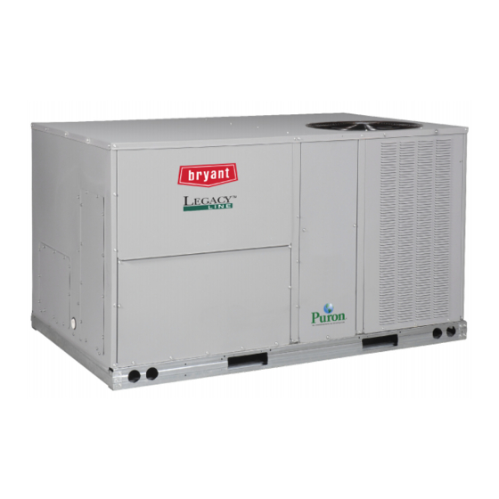
(Optional hail guard shown.)
This product has been designed and manufactured to
meet Energy Star® criteria for energy efficiency.
However, proper refrigerant charge and proper air flow
are critical to achieve rated capacity and efficiency.
Installation of this product should follow all
manufacturer's refrigerant charging and air flow
instructions. Failure to confirm proper charge and
air flow may reduce energy efficiency and shorten
equipment life.
the environmentally sound refrigerant
C08515
Advertisement
Table of Contents

Subscribe to Our Youtube Channel
Related Manuals for Bryant PACKAGED HEAT PUMP 548J


Summary of Contents for Bryant PACKAGED HEAT PUMP 548J
-
Page 1: Product Data
548J PACKAGED HEAT PUMP 3 TO 8.5 NOMINAL TONS This product has been designed and manufactured to meet Energy Star® criteria for energy efficiency. However, proper refrigerant charge and proper air flow are critical to achieve rated capacity and efficiency. -
Page 2: Table Of Contents
Convertible airflow design makes it easy to adjust to unexpected job- - site complications. Lighter units make easy replacement. Bryant 3- - 8.5 ton 548J rooftops fit on existing Bryant curbs dating back to 1989. Also, our large control box gives you room to work and room to mount Bryant accessory controls. -
Page 3: Features And Benefits
S Up to 28% lighter than similar industry units. Lighter rooftops make easier replacement jobs. S 3- - 8.5 ton units fit on existing Bryant rooftop curbs making the utility connections the same. This saves time and money on replacement jobs. -
Page 4: Model Number Nomenclature
MODEL NUMBER NOMENCLATURE 5 4 8 J P 0 6 A 0 0 0 A 0 B 0 A A -- ____________ Unit Type 548J = High Eff. Heat Pump Voltage E = 460--- 3--- 60 J = 208/230--- 1--- 60... - Page 5 FACTORY OPTIONS AND/OR ACCESSORIES Table 1 – FACTORY- - INSTALLED OPTIONS AND FIELD- - INSTALLED ACCESSORIES CATEGORY Cabinet Thru--- the--- base electrical connections Cu/Cu indoor and/or outdoor coils Coil Options Pre--- coated outdoor coils Premium, E--- coated outdoor coils Condenser Protection Condenser coil hail guard (louvered design) Thermostats, temperature sensors, and subbases RTU--- MP Multi--- protocol controller...
- Page 6 Motorized 2- - Position Damper The new Bryant 2- - position, motorized outdoor air damper admits up to 100% outside air. Using reliable, gear- - driven technology, the 2- - position damper opens to allow ventilation air and closes when the rooftop stops, stopping unwanted infiltration.
-
Page 7: Electric Heaters
Electric Heaters Bryant offers a full- - line of field- - installed accessory heaters. The heaters are very easy to use, install and are all pre- - engineered and certified. - Page 8 Table 2 – ARI COOLING RATING TABLES NOMINAL NET COOLING 548J* CAPACITY (TONS) NOTE: All AHRI ratings are based on 230, 460 and 575 volt. Electric Drive (direct drive) X13 5 speed/torque motor. SEER rating is 13.0 for belt drive. Not applicable 548J* HSPF...
-
Page 9: Sound Performance
3. A--- weighted sound ratings filter out very high and very low frequencies, to better approximate the response of an “aver- age” human ear. A--- weighted measurements for Bryant units are taken in accordance with 270--- 95. ELECTRIC HEATERS... -
Page 10: Physical Data
Table 5 – PHYSICAL DATA Refrigeration System # Circuits / # Comp. / Type Puronr refrig. (R--- 410A) charge per circuit A/B (lbs--- oz) Metering Device High--- pressure Trip / Reset (psig) Loss of Charge Pressure Trip / Reset (psig) Evap. - Page 11 Table 6 – PHYSICAL DATA Refrigeration System # Circuits / # Comp. / Type Puronr refrig. (R--- 410A) charge per circuit A/B (lbs--- oz) Metering Device High--- pressure Trip / Reset (psig) Loss of Charge Pressure Trip / Reset (psig) Evap.
- Page 12 Table 7 – ELECTRIC HEAT - - ELECTRICAL DATA ELECTRIC HEATER PART NUMBER TYPE CRHEATERXXXXXX 101A00 102A00 103B00 104B00 102A00,102A00 101A00 102A00 103B00 104B00 105A00 101A00 102A00 103B00 104B00 105A00 101A00 102A00 HIGH 103B00 104B00 105A00 106A00 107A00 108A00 109A00 106A00 107A00 108A00...
- Page 13 Table 7 - - (cont.) ELECTRIC HEAT - - ELECTRICAL DATA ELECTRIC HEATER PART NUMBER TYPE CRHEATERXXXXXX 101A00 103B00 102A00,102A00 103B00,103B00 104B00,104B00 102A00 103B00 105A00 104B00,104B00 102A00 103B00 105A00 104B00,104B00 102A00 103B00 HIGH 105A00 104B00,104B00 106A00 108A00 109A00 108A00,108A00 106A00 108A00 109A00 108A00,108A00...
- Page 14 Table 7 - - (cont.) ELECTRIC HEAT - - ELECTRICAL DATA ELECTRIC HEATER PART NUMBER TYPE CRHEATERXXXXXX 102A00 103B00 102A00,102A00 103B00,103B00 104B00,104B00 102A00 104B00 105A00 104B00,104B00 104B00,105A00 102A00 104B00 105A00 104B00,104B00 104B00,105A00 102A00 104B00 HIGH 105A00 104B00,104B00 104B00,105A00 106A00 108A00 109A00 108A00,108A00 108A00,109A00...
- Page 15 Table 7 - - (cont.) ELECTRIC HEAT - - ELECTRICAL DATA ELECTRIC HEATER PART NUMBER TYPE CRHEATERXXXXXX 102A00 104B00 105A00 104B00,104B00 104B00,105A00 102A00 104B00 105A00 104B00,104B00 104B00,105A00 102A00 104B00 HIGH 105A00 104B00,104B00 104B00,105A00 106A00 108A00 109A00 108A00,108A00 108A00,109A00 106A00 108A00 109A00 108A00,108A00 108A00,109A00...
- Page 16 Table 7 - - (cont.) ELECTRIC HEAT - - ELECTRICAL DATA ELECTRIC HEATER PART NUMBER TYPE CRHEATERXXXXXX 117A00 110A00 111A00 112A00 112A00,117A00 117A00 110A00 111A00 112A00 112A00,117A00 117A00 110A00 HIGH 111A00 112A00 112A00,117A00 116A00 113A00 114A00 115A00 114A00,116A00 116A00 113A00 114A00 115A00 114A00,116A00...
- Page 17 Table 7 - - (cont.) ELECTRIC HEAT - - ELECTRICAL DATA ELECTRIC HEATER PART NUMBER TYPE CRHEATERXXXXXX 117A00 110A00 111A00 112A00 112A00,117A00 117A00 110A00 111A00 112A00 112A00,117A00 117A00 110A00 HIGH 111A00 112A00 112A00,117A00 116A00 113A00 114A00 115A00 114A00,116A00 116A00 113A00 114A00 115A00 114A00,116A00...
-
Page 18: Weights & Dimensions
WEIGHTS & DIMENSIONS C09018 Fig. 1 - - Dimensions 548J 04- -07... - Page 19 WEIGHTS & DIMENSIONS (cont.) DIMENSION 48” (1219 mm) 18” (457 mm) 18” (457 mm) 12” (305 mm) 42” (1067 mm) 36” (914 mm) Special 36” (914 mm) 18” (457 mm) 42” (1067 mm) 36” (914 mm) Fig. 2 - - Dimensions 548J 04- -07 Fig.
- Page 20 WEIGHTS & DIMENSIONS (cont.) ROOFCURB UNIT SIZE ACCESSORY 1’ - 2” CRRFCURB001A01 [356] 548J*04-07A 2’ - 0” CRRFCURB002A01 [610] Fig. 4 - - Curb Dimensions 548J 04- -07 C08560...
- Page 21 WEIGHTS & DIMENSIONS (cont.) Vertical Connections / Economizer Horizontal Connections / Economizer C08679 Fig. 5 - - Dimensions 548J 08- -09...
- Page 22 WEIGHTS & DIMENSIONS (cont.) DIMENSION 48” (1219 mm) 18” (457 mm) 18” (457 mm) 12” (305 mm) 42” (1067 mm) 36” (914 mm) Special 36” (914 mm) 18” (457 mm) 42” (1067 mm) 36” (914 mm) Fig. 6 - - Dimensions 548J 08- -09 Fig.
- Page 23 WEIGHTS & DIMENSIONS (cont.) ROOFCURB UNIT SIZE ACCESSORY 1’ - 2” CRRFCURB003A01 [356] 548J08, 09 548J08, 09 2’ - 0” CRRFCURB004A01 [610] Fig. 8 - - Curb Dimensions 548J 08- -09 C08561...
-
Page 24: Application Data
Please contact your local Bryant representative for assistance. Motor limits, break horsepower (BHP): Due to Bryant’s internal unit design, air path, and specially designed motors, the full horsepower (maximum continuous BHP) band, as listed in this manual, can be used with the utmost confidence. - Page 25 SELECTION PROCEDURE (WITH 548J*07 EXAMPLE) (Selection software by Bryant saves time by performing many of the steps below.) Determine cooling and heating loads. Given: Mixed Air Drybulb Mixed Air Wetbulb Ambient Drybulb Load Load Load Outdoor-Air Winter Design Temp Indoor-Air Winter Design Temp...
- Page 26 Table 8 – COOLING CAPACITIES 548J*04 EA (dB) 31.4 31.4 27.1 31.4 33.5 33.5 24.8 29.6 38.0 38.0 21.0 25.8 42.1 42.1 16.7 21.6 44.9 17.8 33.7 33.7 29.1 33.7 35.0 35.0 26.9 32.5 39.4 39.4 22.4 43.3 43.3 17.2 22.8 45.8 18.4...
- Page 27 Table 9 – COOLING CAPACITIES 548J*05 EA (dB) 41.7 41.7 36.5 41.7 44.1 44.1 33.7 38.9 48.8 48.8 28.2 33.4 53.2 53.2 22.3 27.5 56.2 22.5 44.1 44.1 38.1 44.1 45.8 45.8 36.2 42.3 50.2 50.2 29.7 35.8 54.4 54.4 22.9 28.9 57.1...
- Page 28 Table 10 – COOLING CAPACITIES 548J*06 EA (dB) 52.7 52.7 46.2 52.7 55.5 55.5 42.8 49.3 61.7 61.7 35.6 42.1 68.0 68.0 27.9 34.4 72.9 28.0 56.0 56.0 48.4 56.0 57.6 57.6 46.4 54.0 63.6 63.6 38.0 45.6 69.9 69.9 29.0 36.6 74.6...
- Page 29 Table 11 – COOLING CAPACITIES 548J*07 EA (dB) 61.1 61.1 53.3 61.1 64.1 64.1 49.6 57.4 70.8 70.8 40.7 48.5 77.4 77.4 31.1 38.9 82.0 30.9 64.6 64.6 55.5 64.6 66.1 66.1 53.4 62.5 72.8 72.8 43.1 52.2 79.2 79.2 31.9 41.1 83.1...
- Page 30 Table 12 – COOLING CAPACITIES 548J*08 EA (dB) 77.4 77.4 66.9 77.4 81.8 81.8 60.6 72.1 90.6 90.6 50.4 62.0 99.4 99.4 39.6 51.3 105.7 42.1 81.8 81.8 70.7 81.8 84.7 84.7 65.2 78.5 93.4 93.4 53.4 66.7 101.9 101.9 40.8 54.1 107.7...
- Page 31 Table 13 – COOLING CAPACITIES 548J*09 EA (dB) 91.1 91.1 79.4 91.1 96.0 96.0 72.7 86.0 106.4 106.4 60.4 73.8 117.3 117.3 47.4 60.9 126.1 50.3 96.5 96.5 84.1 96.5 98.2 98.2 78.1 93.6 109.5 109.5 64.1 79.6 120.6 120.6 49.1 64.7 129.2...
- Page 32 Table 14 – HEATING CAPACITIES RETURN (STANDARD AIR) ---10 (°F db) Capacity 11.6 Int. Cap. 10.7 Capacity 12.0 1200 Int. Cap. 11.1 Capacity 12.6 1500 Int. Cap. 11.6 Capacity Int. Cap. Capacity 10.1 1200 Int. Cap. Capacity 10.8 1500 Int. Cap. 10.0 Capacity Int.
- Page 33 Table 16 – HEATING CAPACITY RETURN (STANDARD AIR) ---10 (°F DB) Capacity 22.7 1500 Int. Cap. 21.0 Capacity 22.8 2000 Int. Cap. 21.1 Capacity 24.2 2500 Int. Cap. 22.4 Capacity 19.9 1500 Int. Cap. 18.4 Capacity 20.1 2000 Int. Cap. 18.6 Capacity 21.5...
- Page 34 Table 18 – HEATING CAPACITY RETURN (STANDARD AIR) ---10 (°F db) Capacity 2250 Int. Cap. Capacity 3000 Int. Cap. Capacity 3750 Int. Cap. Capacity 25.9 2250 Int. Cap. 23.9 Capacity 27.4 3000 Int. Cap. 25.3 Capacity 31.0 3750 Int. Cap. 28.6 Capacity 22.5...
-
Page 35: Factory Options & Accessories
5. For information on the electrical properties of Bryant motors, please see the Electrical information section of this book. 6. For more information on the performance limits of Bryant motors, see the application data section of this book. 3 --- 6 TONS... -
Page 36: Fan Performance
Table 21 – 548J*04 ELECTRIC DRIVE, X13 MOTOR, 3 TON HORIZONTAL SUPPLY SPEED (TORQUE) 0.70 0.60 1050 0.50 1125 0.39 1200 0.29 1275 0.21 1350 0.12 1425 0.03 1500 0.85 0.76 1050 0.66 1125 0.55 1200 0.46 1275 0.36 1350 0.27 1425 0.17... - Page 37 Table 23 – 548J*05 ELECTRIC DRIVE, X13 MOTOR, 4 TON HORIZONTAL SUPPLY SPEED (TORQUE) 1200 0.75 1300 0.63 1400 0.48 1500 0.33 1600 0.19 1700 0.05 1800 1900 2000 1200 0.97 1300 0.88 1400 0.77 1500 0.64 1600 0.50 1700 0.36 1800 0.21...
- Page 38 Table 25 – 548J*06 ELECTRIC DRIVE, X13 MOTOR, 5 TON HORIZONTAL SUPPLY SPEED (TORQUE) 1500 1.19 1625 1.01 1750 0.82 1875 0.60 2000 0.38 2125 0.16 2250 2375 2500 1500 1.40 1625 1.25 1750 1.08 1875 0.90 2000 0.67 2125 0.44 2250 0.20...
- Page 39 Table 27 – 548J*04 0.13 0.15 1050 0.18 1125 0.20 0.23 1200 1275 0.26 1350 0.30 0.34 1425 0.38 1500 1078 0.77 1151 1093 0.80 1165 1050 1108 0.84 1180 1125 1123 0.88 1195 1200 1140 0.92 1210 1275 1157 0.97 1226 1350...
- Page 40 Table 29 – 548J*05 0.23 1200 1300 0.28 1400 0.33 0.38 1500 1600 0.45 1700 0.52 1800 0.60 1900 0.69 1019 2000 0.78 1054 1200 1140 0.92 1210 1300 1162 0.99 1232 1400 1186 1.06 1254 1500 1210 1.14 1278 1600 1236 1.23...
- Page 41 Table 31 – 548J*06 0.33 1500 1625 0.40 1750 0.48 0.57 1875 2000 0.66 2125 0.78 1027 0.90 2250 1067 2375 1018 1.03 1107 2500 1061 1.19 1148 1500 1172 1.06 1239 1625 1201 1.16 1267 1750 1231 1.28 1296 1875 1262 1.41...
- Page 42 Table 33 – 548J*07 1800 1950 2100 0.75 1019 2250 0.90 1067 2400 1026 1.06 1115 2550 1079 1.25 1164 2700 1132 1.46 1214 2850 1186 1.69 1264 3000 1240 1.94 1315 1800 1244 1.33 1308 1950 1281 1.49 1345 2100 1320 1.67...
- Page 43 Table 35 – 548J*08 2250 2438 2625 0.40 2813 0.47 3000 0.55 3188 0.65 3375 0.75 3563 0.86 3750 0.99 2250 0.94 2438 1.03 2625 1.13 2813 1.24 3000 1.36 3188 1.49 3375 1.63 3563 1.78 3750 1.94 Std static motor and drive (belt drive) Med static motor and drive (belt drive) High static motor and drive (belt drive) Table 36 –...
- Page 44 Table 37 – 548J*09 2550 0.39 2763 0.47 2975 0.57 3188 0.68 3400 0.80 3613 0.94 3825 1.09 4038 1.26 4250 1.45 2550 1.11 2763 1.24 2975 1.37 3188 1.53 3400 1.69 3613 1.87 3825 2.07 4038 2.28 4250 2.51 Std static motor and drive (belt drive) Med static motor and drive (belt drive) High static motor and drive (belt drive)
- Page 45 Table 39 – PULLEY ADJUSTMENT UNIT MOTOR/DRIVE COMBO Medium Static 1251 High Static 1466 Medium Static 1303 High Static 1466 Medium Static 1380 High Static 1639 Standard Static 1192 Medium Static 1380 High Static 1639 Standard Static Medium Static High Static 1084 Standard Static Medium Static...
- Page 46 ECONOMIZER, BAROMETRIC RELIEF AND PE PERFORMANCE 2500 2000 1500 1000 0.05 0.15 0.25 RETURN DUCT STATIC PRESS URE (in. wg) Fig. 9 - - Barometric Relief Flow Capacity 0.00 0.10 0.20 0.30 0.40 0.50 STATIC PRESS URE DELTA (in. wg) Fig.
-
Page 47: Electrical Info
ELECTRICAL INFORMATION Table 40 – 548J*04 VOLTAGE COMP (ea) RANGE V- - Ph- - Hz 208- -1- -60 17.9 230- -1- -60 17.9 208- -3- -60 13.2 230- -3- -60 13.2 460- -3- -60 575- -3- -60 Table 41 – 548J*05 VOLTAGE COMP (ea) RANGE... - Page 48 ELECTRICAL INFORMATION (cont.) Table 43 – 548J*07 VOLTAGE COMP (ea) RANGE V ---Ph---Hz 208--- 3--- 60 19.0 230--- 3--- 60 19.0 460--- 3--- 60 575--- 3--- 60 Table 44 – 548J*08 COMP (Cir 1) VOLTAGE RANGE V ---Ph---Hz 208--- 3--- 60 13.1 230--- 3--- 60 13.1...
-
Page 49: Mca / Mocp
Table 46 – MCA/MOCP DETERMINATION WITHOUT C.O. OR UNPWRD C.O. ELEC. HTR TYPE (kW) 3.3/4.4 15.9/18.3 4.9/6.5 23.5/27.1 DD--- STD 6.5/8.7 31.4/36.3 7.9/10.5 37.9/43.8 9.8/13.0 46.9/54.2 3.3/4.4 9.2/10.6 4.9/6.5 13.6/15.6 DD--- STD 6.5/8.7 18.1/20.9 7.9/10.5 21.9/25.3 12.0/16.0 33.4/38.5 3.3/4.4 9.2/10.6 4.9/6.5 13.6/15.6 6.5/8.7... - Page 50 Table 46 – (cont.) MCA/MOCP DETERMINATION WITHOUT C.O. OR UNPWRD C.O. ELEC. HTR TYPE (kW) 3.3/4.4 15.9/18.3 6.5/8.7 31.4/36.3 DD--- STD 9.8/13.0 46.9/54.2 13.1/17.4 62.8/72.5 15.8/21.0 75.8/87.5 4.9/6.5 13.6/15.6 DD--- STD 6.5/8.7 18.1/20.9 12.0/16.0 33.4/38.5 15.8/21.0 43.8/50.5 4.9/6.5 13.6/15.6 6.5/8.7 18.1/20.9 12.0/16.0 33.4/38.5...
- Page 51 Table 46 – (cont.) MCA/MOCP DETERMINATION WITHOUT C.O. OR UNPWRD C.O. ELEC. HTR TYPE (kW) 4.9/6.5 23.5/27.1 6.5/8.7 31.4/36.3 DD--- STD 9.8/13.0 46.9/54.2 13.1/17.4 62.8/72.5 15.8/21.0 75.8/87.5 4.9/6.5 13.6/15.6 7.9/10.5 21.9/25.3 DD--- STD 12.0/16.0 33.4/38.5 15.8/21.0 43.8/50.5 19.9/26.5 55.2/63.8 4.9/6.5 13.6/15.6 7.9/10.5 21.9/25.3...
- Page 52 Table 46 – (cont.) MCA/MOCP DETERMINATION WITHOUT C.O. OR UNPWRD C.O. ELEC. HTR TYPE (kW) 4.9/6.5 13.6/15.6 7.9/10.5 21.9/25.3 12.0/16.0 33.4/38.5 15.8/21.0 43.8/50.5 19.9/26.5 55.2/63.8 4.9/6.5 13.6/15.6 7.9/10.5 21.9/25.3 12.0/16.0 33.4/38.5 15.8/21.0 43.8/50.5 19.9/26.5 55.2/63.8 4.9/6.5 13.6/15.6 7.9/10.5 21.9/25.3 HIGH 12.0/16.0 33.4/38.5 15.8/21.0...
- Page 53 Table 46 – (cont.) MCA/MOCP DETERMINATION WITHOUT C.O. OR UNPWRD C.O. ELEC. HTR TYPE (kW) 7.8/10.4 21.7/25.0 12.0/16.0 33.4/38.5 18.6/24.8 51.7/59.7 24.0/32.0 66.7/77.0 31.8/42.4 88.4/102.0 7.8/10.4 21.7/25.0 12.0/16.0 33.4/38.5 18.6/24.8 51.7/59.7 24.0/32.0 66.7/77.0 31.8/42.4 88.4/102.0 7.8/10.4 21.7/25.0 12.0/16.0 33.4/38.5 HIGH 18.6/24.8 51.7/59.7 24.0/32.0...
- Page 54 Table 46 – (cont.) MCA/MOCP DETERMINATION WITHOUT C.O. OR UNPWRD C.O. ELEC. HTR TYPE (kW) 7.8/10.4 21.7/25.0 12.0/16.0 33.4/38.5 18.6/24.8 51.7/59.7 24.0/32.0 66.7/77.0 31.8/42.4 88.4/102.0 7.8/10.4 21.7/25.0 12.0/16.0 33.4/38.5 18.6/24.8 51.7/59.7 24.0/32.0 66.7/77.0 31.8/42.4 88.4/102.0 7.8/10.4 21.7/25.0 12.0/16.0 33.4/38.5 HIGH 18.6/24.8 51.7/59.7 24.0/32.0...
- Page 55 Table 47 – MCA/MOCP DETERMINATION WITH PWRD C.O. ELEC. HTR TYPE (kW) 3.3/4.4 15.9/18.3 4.9/6.5 23.5/27.1 DD--- STD 6.5/8.7 31.4/36.3 7.9/10.5 37.9/43.8 9.8/13.0 46.9/54.2 3.3/4.4 9.2/10.6 4.9/6.5 13.6/15.6 DD--- STD 6.5/8.7 18.1/20.9 7.9/10.5 21.9/25.3 12.0/16.0 33.4/38.5 3.3/4.4 9.2/10.6 4.9/6.5 13.6/15.6 6.5/8.7 18.1/20.9 7.9/10.5...
- Page 56 Table 47– (cont.) MCA/MOCP DETERMINATION WITH PWRD C.O. ELEC. HTR TYPE (kW) 3.3/4.4 15.9/18.3 6.5/8.7 31.4/36.3 DD--- STD 9.8/13.0 46.9/54.2 13.1/17.4 62.8/72.5 15.8/21.0 75.8/87.5 4.9/6.5 13.6/15.6 DD--- STD 6.5/8.7 18.1/20.9 12.0/16.0 33.4/38.5 15.8/21.0 43.8/50.5 4.9/6.5 13.6/15.6 6.5/8.7 18.1/20.9 12.0/16.0 33.4/38.5 15.8/21.0 43.8/50.5 4.9/6.5...
- Page 57 Table 47 – (cont.) MCA/MOCP DETERMINATION WITH PWRD C.O. ELEC. HTR TYPE (kW) 4.9/6.5 23.5/27.1 6.5/8.7 31.4/36.3 DD--- STD 9.8/13.0 46.9/54.2 13.1/17.4 62.8/72.5 15.8/21.0 75.8/87.5 4.9/6.5 13.6/15.6 7.9/10.5 21.9/25.3 DD--- STD 12.0/16.0 33.4/38.5 15.8/21.0 43.8/50.5 19.9/26.5 55.2/63.8 4.9/6.5 13.6/15.6 7.9/10.5 21.9/25.3 12.0/16.0 33.4/38.5...
- Page 58 Table 47 – (cont.) MCA/MOCP DETERMINATION WITH PWRD C.O. ELECTRIC HEATER TYPE (kW) 4.9/6.5 13.6/15.6 7.9/10.5 21.9/25.3 12.0/16.0 33.4/38.5 15.8/21.0 43.8/50.5 19.9/26.5 55.2/63.8 4.9/6.5 13.6/15.6 7.9/10.5 21.9/25.3 12.0/16.0 33.4/38.5 15.8/21.0 43.8/50.5 19.9/26.5 55.2/63.8 4.9/6.5 13.6/15.6 7.9/10.5 21.9/25.3 HIGH 12.0/16.0 33.4/38.5 15.8/21.0 43.8/50.5 19.9/26.5...
- Page 59 Table 47 – (cont.) MCA/MOCP DETERMINATION WITH PWRD C.O. ELECTRIC HEATER TYPE (kW) 7.8/10.4 21.7/25.0 12.0/16.0 33.4/38.5 18.6/24.8 51.7/59.7 24.0/32.0 66.7/77.0 31.8/42.4 88.4/102.0 7.8/10.4 21.7/25.0 12.0/16.0 33.4/38.5 18.6/24.8 51.7/59.7 24.0/32.0 66.7/77.0 31.8/42.4 88.4/102.0 7.8/10.4 21.7/25.0 12.0/16.0 33.4/38.5 HIGH 18.6/24.8 51.7/59.7 24.0/32.0 66.7/77.0 31.8/42.4...
- Page 60 Table 47 – (cont.) MCA/MOCP DETERMINATION WITH PWRD C.O. ELECTRIC HEATER TYPE (kW) 7.8/10.4 21.7/25.0 12.0/16.0 33.4/38.5 18.6/24.8 51.7/59.7 24.0/32.0 66.7/77.0 31.8/42.4 88.4/102.0 7.8/10.4 21.7/25.0 12.0/16.0 33.4/38.5 18.6/24.8 51.7/59.7 24.0/32.0 66.7/77.0 31.8/42.4 88.4/102.0 7.8/10.4 21.7/25.0 12.0/16.0 33.4/38.5 HIGH 18.6/24.8 51.7/59.7 24.0/32.0 66.7/77.0 31.8/42.4...
-
Page 61: Typical Wiring Diagrams
TYPICAL WIRING DIAGRAMS C09063 Fig. 17 - - 1- -Stage Cooling Typical Power Diagram... - Page 62 C09065 Fig. 18 - - 2- -Stage Cooling Typical Power Diagram...
- Page 63 C09067 Fig. 19 - - Multi- -Protocol Option Diagram...
-
Page 66: Sequence Of Operation
Cooling, unit without economizer When thermostat calls for cooling, terminals G and Y1 are energized. The indoor-fan contactor (IFC), reversing valve solenoid (RVS) and compressor contactor are energized and indoor-fan motor, compressor, and outdoor fan starts. The outdoor fan motor runs continuously while unit is cooling. - Page 67 At the end of the defrost cycle, the electric heaters (if installed) will be deenergized; the reversing valves switch and the outdoor-fan motor will be energized. The unit will now operate in the Heating mode. If the space thermostat is satisfied during a defrost cycle, the unit will continue in the Defrost mode until the time or temperature constraints are satisfied.
-
Page 68: Guide Specifications
GUIDE SPECIFICATIONS - - 548J*04- -09 Note about this specification: Bryant created this specification in “Masterformat” as published by the Construction Specification Institute. Please feel free to copy this specification directly into your building specifications. Rooftop Packaged Heat Pump HVAC Guide Specifications Size Range: 3 to 8.5 Nominal Tons... - Page 69 13. Shall include an EIA- - 485 protocol communication port, an access port for connection of either a computer or a Bryant technician tool, an EIA- - 485 port for network communication to intelligent space sensors and displays, and a port to connect an optional LonWorks communications card.
- Page 70 1. Outdoor, rooftop mounted, electrically controlled, heating and cooling unit utilizing a(n) hermetic scroll com- pressor(s) for cooling duty and heat pump for heating duty. 2. Factory assembled, single- - piece heating and cooling rooftop unit. Contained within the unit enclosure shall be all factory wiring, piping, controls, and special features required prior to field start- - up.
- Page 71 5. Unit shall be factory configured for vertical supply & return configurations. 6. Unit shall be field convertible from vertical to horizontal configuration 7. Unit shall be capable of mixed operation: vertical supply with horizontal return or horizontal supply with vertical return.
- Page 72 2. Optional Pre- - coated aluminum- - fin condenser coils: on all models. a. Shall have a durable epoxy- - phenolic coating to provide protection in mildly corrosive coastal environments. b. Coating shall be applied to the aluminum fin stock prior to the fin stamping process to create an inert barrier between the aluminum fin and copper tube.
- Page 73 3. Shall consist of factory- - installed, low velocity, throw- - away 2- - in. thick fiberglass filters. 4. Filters shall be standard, commercially available sizes. 5. Only one size filter per unit is allowed. 23 81 19.13.M. Evaporator Fan and Motor 1.
- Page 74 n. Economizer controller shall accept a 2- - 10Vdc CO shall modulate the outdoor- - air damper to provide ventilation based on the sensor input. o. Compressor lockout sensor shall open at 35_F (2_C) and closes at 50_F (10_C). p. Actuator shall be direct coupled to economizer gear. No linkage arms or control rods shall be acceptable. q.
- Page 75 9. Fan/Filter Status Switch: a. Switch shall provide status of indoor evaporator fan (ON/OFF) or filter (CLEAN/DIRTY). b. Status shall be displayed either over communication bus (when used with direct digital controls) or with an indicator light at the thermostat. 10.
- Page 76 (minimum 18 ga galvanized steel) attached to end of heater assembly. E2009 Bryant Heating & Cooling Systems D 7310 W. Morris St. D Indianapolis, IN 46231 Manufacturer reserves the right to discontinue, or change at any time, specifications or designs without notice and without incurring obligations.
Need help?
Do you have a question about the PACKAGED HEAT PUMP 548J and is the answer not in the manual?
Questions and answers