Table of Contents
Advertisement
Quick Links
Advertisement
Table of Contents

Related Manuals for Coolmax CF-350B


Summary of Contents for Coolmax CF-350B
- Page 1 Table of Content...
-
Page 2: Function Description
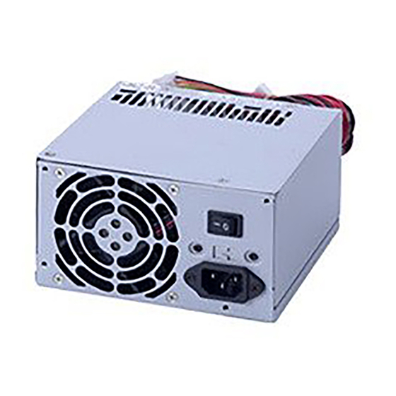
Follow the steps below to finish the installation. Step1: Open the computer tower cover; put the power supply into the corresponding location of the tower, and then use right screws to fix the power supply to tower. Step2: Put the Main Power Connector, ATX12V Connector, S-ATAonnector, Peripheral Connectors and Floppy Connectors to the corresponding male connectors of main-board, peripheral devices (i.e. -
Page 3: Inrush Current
FL-350ATX(CF-350) FL-420ATX(CF-400) FL-480ATX(CF-480) 3.5. Efficiency The power supply efficiency shall not be less than 75% at the maximum load of section 4.2 and 115/230Vac input voltage. While at half load the value shall reach 77% min. Volt Selector Set Limits NO component over stress or damage should occur to the power supply. - Page 4 4. Output 4.1. Output Regulations Output Range Voltage +12V -12V +3.3V +5Vsb Note: The output voltage should be measured at the terminals of output connector. 4.2. Power Distribution Configuration FL-550ATX (CF-300) Output Rail Max. 300W +3.3V +12V 0.3A -12V 0.8A +5Vsb 4.3.
- Page 5 30, the AC input should be nominal input. 4.6. Remote ON/OFF Control The power supply outputs shall be enabled with an active-low TTL signal. When TTL signal is low, the DC outputs are to be enabled. When TTL signal is high or open circuited, the DC outputs are to be disabled. Electronic means or a mechanical switch may activate the TTL signal.
- Page 6 PS-ON signal MIN. 5. Protections 5.1. Over Voltage Protection When the DC outputs (+5V, +12V and +3.3V) have over voltage condition, the power supply shall provide latch mode over voltage protection. DC Output +12V +3.3V Units MAX.
-
Page 7: Short Circuit Protection
At 115/230Vac input the power supply will shut down all DC output within 110% to 160% of full load. 5.6. Over Temperature Protection The power supply shall go to latch when its inner teperat ure reaches 100 degree C. 6. Enviroment 6.1. -
Page 8: Regulatory Compliance
The power supply shall have a minimum MTBF at continuous operation of 50,000 hours at 100% load, the recommended ambient temperature of 25 degree C and a maximum inner temperature of the power supply at 80 degree C for 230Vac/50Hz and 115Vac/60Hz 10. -
Page 9: Simple Maintenance
11.4 Please check the output connectors plugging in proper direction and connecting firmly. 11.5. Having checked above items, if the power supply still does not function, please send it back to your retailer or distributor for repair 12. Power Connector Drawing... - Page 10 13. Cable adaptor drawing 1007 20# ORANGE 1007 18# BLUE 1007 18# BLACK 1007 18# GREEN 1007 18# BLACK 1007 18# BLACK 1007 18# BLACK 1007 18# W HITE 1007 18# RED 1007 20# RED 1007 20# RED 1007 20# BLACK 1 007 20# ORANGE 1 007 20# YE LLOW 10 07 20# YELLOW...
Need help?
Do you have a question about the CF-350B and is the answer not in the manual?
Questions and answers