Hubble AM-2 Manual
Integrated lithium-ion battery
Hide thumbs
Also See for AM-2:
- Manual (12 pages) ,
- Quick installation manual (2 pages) ,
- Manual (10 pages)

Related Manuals for Hubble AM-2


Summary of Contents for Hubble AM-2
- Page 1 HUBBLE LITHIUM AM-2 MANUAL Integrated Lithium-ion Battery Manual for Hubble AM-2 Version:V1.0 Released Date:2021-04-02...
-
Page 2: Table Of Contents
Content Appearance ................................3 Installation ................................4 Dip switch settings ..............................4 Connections ................................5 DC Isolator ................................5 Inverter Setup (Pre launch) ............................ 5 CAN Bus Setup (Optional) ............................6 Completing Setup ..............................6 LED Indication................................. 7 10. BMS Low Power Mode ............................8 11. -
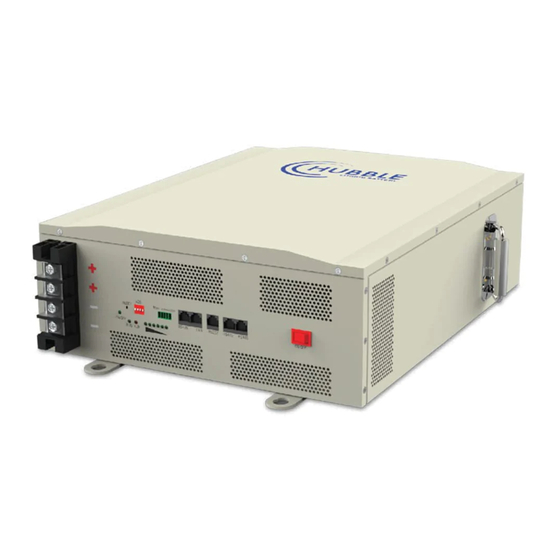
Page 3: Appearance
1. Appearance Below illustration of the AM-2 model. -
Page 4: Installation
2. Installation The AM-2 is designed to be wall mounted or installed flat inside a cabinet. The unit is not designed to be installed upside down or sideways on a wall. When installing on a wall ensure you use Rawl bolts to secure the unit onto the wall. -
Page 5: Connections
100%. 5. DC Isolator The Hubble AM series of batteries has an integrated electronic circuit breaker built into the BMS. The integrated electronic CB is for protecting the battery and the internal cells against overload, over current, over volt etc. -
Page 6: Can Bus Setup (Optional)
The AM series models has an integrated CAN bus port on each battery. The CAN bus can be used to connect to any inverter that is CAN bus ready. The Hubble range of lithium batteries with CAN bus port can integrate with most leading inverters. -
Page 7: Led Indication
9. LED Indication Table 1: LED Operation Status Normal / SOC Indication LEDs Status Alarm / Remark ● ● ● ● ● ● Protection Power Off Sleep All off Normal Flash 1 Standby state Standby Indication by SOC Alarm Flash 1 Flash 3 Cell low voltage Normal... -
Page 8: 10. Bms Low Power Mode
Push the switch for 6 seconds, the BMS will reset. LEDs will flash one at the same. 10. BMS Low Power Mode The Hubble BMS will enter low power mode if the following conditions happen: • When over-discharge protection has occurred. (30S later). -
Page 9: 13. Data Storage
14. Maintenance The Hubble BMS will protect the battery and life of your battery as best possible. However, it must be noted that proper operation of the battery is recommended, and maintenance functions should be taken to ensure the maximum life of your batteries.
Need help?
Do you have a question about the AM-2 and is the answer not in the manual?
Questions and answers