
Related Manuals for Enotec COMTEC 6000


Summary of Contents for Enotec COMTEC 6000
- Page 1 Installation and Operation Manual / COe Analyzer System ® COMTEC 6000 Version 18 for software version: 4.13 Doc.-ID: COM6000_11022020_EN...
- Page 2 All ENOTEC instruments are thoroughly tested in the factory and are subject to a strict ISO9001 Quality Assurance Procedure.
-
Page 3: Table Of Contents
Wiring diagram of the Electronic Unit ....12 Replacing the probe .......... 38 Wiring Diagram of the COMTEC 6000 System . 13 Exchange of Probe Inner Part ......39 Installation of the probe ........14 ... -
Page 4: System Description
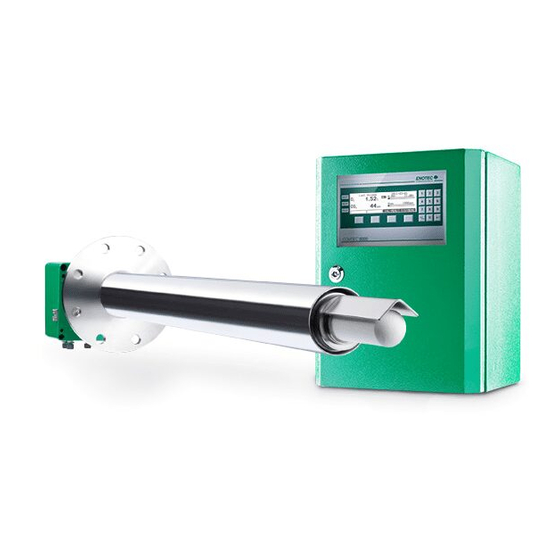
System Description System Overview of the COMTEC 6000 Figure 1 - System overview of the COMTEC 6000 for flue gas temperatures of up to 600° C Safe Area - Max. ambient temp.: -20 °C to +55 °C Electronic unit SME5 / IP66 (-4 °F to + 131 °F) - Page 5 ® Installation and Operation Manual - COMTEC 6000 Figure 2 - System overview of the COMTEC 6000 with cooling protection tube for flue gas temperatures of up to 1400° C Safe Area - Max. ambient temp.:-20 °C to +55 °C Elektronik SME5 / IP66 (-4 °F to + 131 °F)
-
Page 6: Measuring Principles
The O sensor of the COMTEC 6000 is at the tip of the probe and is regulated to 800 °C and works on the zirconium oxide principle of measurement. Here, a mV signal between the reference gas side of the sensor (inside, instrument air 20.95% O... -
Page 7: Safety Hazards
Storage instructions ENOTEC equipment and spares are to be stored in a dry and ventilated environment at temperatures between -40 °C to +80 °C (-40 °F to 176 °F). Paint fumes, silicone sprays, etc. must be avoided in the storage environment. -
Page 8: Name Plates
System Description ® Installation and Operation Manual - COMTEC 6000 Name Plates The name plate contains information about the line voltage, the nominated current, frequency, protection class, year of manufacture, serial number, order number and system order code. The system order code refers to information which is detailed in the system test report and supplied with the system. SME-53 Probe Connection SME-57... -
Page 9: Installation
Installation ® Installation and Operation Manual - COMTEC 6000 Installation Warning The electronic unit does not have a line voltage main switch. The line voltage power supply requires a switch or breaker. The line voltage switch/fuse/breaker must be in accordance with the local technical standards and should be in close proximity to the electronic unit and must be identifiable as such. -
Page 10: Installation Of Probe Signal Cable Fep-0007/8
Figure 5 - Probe cable FEP-0007 Caution Only use ENOTEC probe cables, as the thermocouple cables 2a and 2b are compensating cables and are necessary for correct measurement. The shield of the probe cable must only be connected at the electronic housing at the PE terminal. Under no circumstance should the shield also be connected at the probe. -
Page 11: Access To The Terminals
Installation ® Installation and Operation Manual - COMTEC 6000 Access to the Terminals Warning Before removing the terminal covers, switch off the mains voltage to the system. Switch the mains volt- age on only after attaching the terminal cover. After the installation has been completed, live parts may no longer be accessible. - Page 12 Installation ® Installation and Operation Manual - COMTEC 6000 Wiring diagram of the Electronic Unit Figure 6 - Wiring diagram of the electronic unit Ferrite sleeves (Enclosed) Analogue output cable (customer) Power supply cable (customer) Status signal cable (customer) Probe signal cable Internal Power supply phase Relay contacts for status signals -...
-
Page 13: Wiring Diagram Of The Comtec 6000 System
Installation ® Installation and Operation Manual - COMTEC 6000 Wiring Diagram of the COMTEC 6000 System Figure 7 - Wiring diagram of the COMTEC 6000 Doc.-ID: COM6000_11022020_EN... -
Page 14: Installation Of The Probe
For probe lengths exceeding 2000 mm, a support must be mounted inside the duct (every 2 m) to prevent the probe and mounting tube from flexing or bending. ENOTEC recommends installing the probe horizontally (- 1 ° to - 3 °) for the fastest possible response time. -
Page 15: Adjustment Of The Probe Filter Head
Installation ® Installation and Operation Manual - COMTEC 6000 Adjustment of the Probe Filter Head Info Determine the flow direction of the process gas at the place of installation. Unscrew the retaining ring (clock- wise) with a hook wrench ... -
Page 16: Insulating The Protection Tube Outside The Duct
Installation ® Installation and Operation Manual - COMTEC 6000 2.11 Insulating the Protection Tube outside the Duct Info If a cooling protection tube is used, the part of the protection tube outside the duct wall must be insulated or heated if necessary. If only a protection tube is in use and not a cooling protection tube, this insulation may also be necessary. -
Page 17: Electrical Connections Of The Probe
Installation ® Installation and Operation Manual - COMTEC 6000 2.12 Electrical Connections of the Probe Info The Probe Signal Cable FEP-0007/8 has to be connected to the terminal board in the probe terminal box. Do not connect the shield here. 1 2 3 4 6 9 10 11 12 13 14... -
Page 18: Preparation Of The Pneumatic Cable
Installation ® Installation and Operation Manual - COMTEC 6000 2.14 Preparation of the pneumatic Cable Pneumatic tubing of the pneumatic cable FEP-0002 Clamp ring Support sleeve Both, the pneumatic tubing for the reference air (blue) and the test gas (green) have to be prepared with support sleeves , clamp rings... -
Page 19: Pneumatic Connections Of Electronic Units
Installation ® Installation and Operation Manual - COMTEC 6000 2.16 Pneumatic Connections of Electronic Units Tube Pump version Instrument air version 1/4“ Testgas in Testgas in 1/4“ Testgas out Testgas out 1/4“ Reference air in Instrument air in 1/4“ Reference air out Reference air out 1/4“... -
Page 20: Initial Operation
Switch on the line voltage to the system. After a short power up information, the user is prompted to Select language, set the System date, System time, enter a TAG number and ENOTEC REMOTE code (only if option ENOTEC REMOTE is factory activated) and the cable length. -
Page 21: Display - Measuring Mode
Initial Operation ® Installation and Operation Manual - COMTEC 6000 Display - Measuring Mode TAG number Measured values Active measuring range Blinking indicators showing under or over measuring range Last access Measured components Limit alarm indicators * Only if the limit alarms are switched on and the limits are within min-Alarm / max-Alarm * the set measuring range. -
Page 22: Software Overview And Explanations
Software Overview and Explanations ® Installation and Operation Manual - COMTEC 6000 Software Overview and Explanations Software Overview - SYS-MENU SYS-MENU System Information Actual measured values measured value (% O ) {may be ppm} -mA output 17A/B (mA) sensor input (mV) measured value (ppm or mg/m mA output (mA) sensor input (mV) - Page 23 (mV) Device operating data Powers on counter Hours in operation Min. internal temperature Max. internal temperature Software version and options Software COMTEC 6000 ~~ Options ~~ ♦ ..SYS-MENU System configuration Measuring ranges Meas.range 1 from (% O Meas.range 1 to (% O...
- Page 24 Software Overview and Explanations ® Installation and Operation Manual - COMTEC 6000 limit alarms Limit alarm 1 (O )(OFF/ON) ♦ at } visible when set to "ON" ♦ hysteresis Limit alarm 2 (CO )(OFF/ON) ♦ at } visible when set to "ON" ♦...
- Page 25 System clock/TAG number System date (jjjj-mm-tt) System time (hh:mm:ss) ENOTEC REMOTE settings (optional) } Visible when ENOTEC REMOTE interface is activated ENOTEC REMOTE (ON/OFF) Passkey (8 digit code) } Visible when ENOTEC REMOTE is ON Range (Short / Medium / Maximum) Measuring units Temperature (°C / °F)
-
Page 26: Software Explanations - Sys-Menu
Software Overview and Explanations ® Installation and Operation Manual - COMTEC 6000 Software Explanations - SYS-MENU 4.2.1 Measuring Ranges (Scaling) The O Measuring range is linearly scaled and converted to a linear current output (0/ 4-20 mA). The parameter „O Measuring range from“... -
Page 27: Ma Output On Systerrorsm Errorsrrors (O 2 And Co Errors )
Software Overview and Explanations ® Installation and Operation Manual - COMTEC 6000 4.2.5 mA output on system errors (O and CO Here the mA output value is set corresponding to a measurement error. The measurement output range for the shown value (3,60 mA ..20,40 mA) cannot be defined in this case. 4.2.6 Measuring Ranges (Scaling) The CO... - Page 28 Software Overview and Explanations ® Installation and Operation Manual - COMTEC 6000 4.2.11 Automatic Calibration (ACAL) Automatic calibration enables a cyclic, time-based or remote controlled calibration (using the digital input) of the sensors. The ACAL can be globally switched on or off and can only be started from the main screen of the display. When a 2 Point ACAL is set, a test gas bottle must be permanently connected and turned on.
-
Page 29: Enotec Remote
The device configuration can also not be altered. Range limits the transmission power of the ENOTEC REMOTE module. Maximum = 100m, medium = 10m, short = 1m. The actual possible range may vary due to structural factors and the reception strength of the Smartphone/Tablet. -
Page 30: Load Factory Settings
Software Overview and Explanations ® Installation and Operation Manual - COMTEC 6000 4.2.16 Load factory settings Loading factory settings will restore all original settings and values to the default values programmed in the factory. If activated, all set parameters and also values such as sensor calibration values and calibration results are lost. Take note of the sensor calibration values beforehand and re-enter them after the loading the factory settings. -
Page 31: System Checks
Software Overview and Explanations ® Installation and Operation Manual - COMTEC 6000 System Checks + CO Sensor checks Source: Test air sensor .. mV = .. % sensor .. mV = .. ppm Flow rate .. l/h Source: Test gas sensor ... -
Page 32: Calibration Menu - Display Overview
Software Overview and Explanations ® Installation and Operation Manual - COMTEC 6000 4.4.1 Calibration Menu - Display Overview 1-point calibration display: 2-point calibration displays: Test Gas apply Maximum measuring range is depicted (display jumps between O and CO Representation of measured O value Representation of measured CO value... -
Page 33: 1-Point Calibration (O And/Or Co ) (Manual)
Software Overview and Explanations ® Installation and Operation Manual - COMTEC 6000 4.4.2 1-point calibration (O and/or CO ) (manual) During the 1-point calibration of the sensor, the calibration offset is determined. Test air is hereby applied to the sen- sor. -
Page 34: Service And Maintenance
Service and Maintenance ® Installation and Operation Manual - COMTEC 6000 Service and Maintenance Exchange fuses Warning De-energize the system first! Abb. 26 Position of the fuses fuse system voltage ampere nominal voltage characteristic Size 115 / 230 V AC 0.5 A 250 V AC T / L... -
Page 35: Pressure And Flow Rates For Test Air And/Or Reference Air
Service and Maintenance ® Installation and Operation Manual - COMTEC 6000 Pressure and Flow rates for Test Air and/or Reference Air The systems are factory-set to the correct amounts of test air and/or reference air. The instrument air versions are designed for an inlet pressure of 2-10 bars. With a higher inlet pressure of 6 bar, it is necessary to readjust the flow of reference air and/or test air. -
Page 36: Position Of The Adjustment Valves
Service and Maintenance ® Installation and Operation Manual - COMTEC 6000 Position of the adjustment valves Figure 29 - Terminal cover of the SME-53 electronic unit showing the position of the reference air and test air valves below Adjusting Flow Rate (SME-54) With systems in 19“... -
Page 37: Replacing The Filter
Figure 33 - Glue the filter in place Info The cement dries at room temperature within 24 hours. Using the cement supplied by ENOTEC, all types of ceramic, basalt and sintered metal filters supplied by can be inserted and fixated. -
Page 38: Replacing The Probe
Service and Maintenance ® Installation and Operation Manual - COMTEC 6000 Replacing the probe Warning Hot Surface The probe may only be removed with heat-insulated gloves. Caution Before replacing the probe, heed all warnings in chapter 5.10- Replacing the CO Sensor ... -
Page 39: Exchange Of Probe Inner Part
Service and Maintenance ® Installation and Operation Manual - COMTEC 6000 Exchange of Probe Inner Part Switch off the electronic unit, take the probe out of the protection tube and wait until it has cooled down. Warning hot surface The probe may only be removed with heat-insulated gloves. Before removing the probe, always switch off the supply voltage to the electronic system. -
Page 40: Replacing The O Sensor
Service and Maintenance ® Installation and Operation Manual - COMTEC 6000 Replacing the O Sensor Warning hot surface The probe may only be removed with heat-insulated gloves. Before removing the probe, always switch off the supply voltage to the electronic system. After removal, store the probe in a safe, protected place and wait until it has cooled down below 35°C/95°F. -
Page 41: Replacing The Co Sensor
Service and Maintenance ® Installation and Operation Manual - COMTEC 6000 5.10 Replacing the CO Sensor Caution Failure to observe this information may destroy the new replacement CO sensor. Disable the CO Sensor (via the software) SYS-MENU System Configuration Set CO measure- ment OFF Switch off the power supply of the analyzer system. -
Page 42: Seal The Co Sensor Guide Tube
Service and Maintenance ® Installation and Operation Manual - COMTEC 6000 Prepare the new CO sensor as follows: Take the clamping ring, the O-ring, retainer ring and the cap nut and cover them over the CO sensor. Note: Mind the position of the bevel. Bevel must face O-ring! Figure 38 - Prepare the new COe sensor ... -
Page 43: Relay Outputs / Functions And Correlation
Service and Maintenance ® Installation and Operation Manual - COMTEC 6000 5.11 Relay Outputs / Functions and Correlation The relay contacts are designed for 24V and 1A AC/DC = (Exception: probe valve) Relay Contact Function System error* Normally closed Signals operation-critical errors X5 (19A/B) Maintenance Normally open... -
Page 44: Status Messages
Status Messages ® Installation and Operation Manual - COMTEC 6000 Status Messages Error Messages Error Relay signal Description Message contact output 2.00 mA, The error can occur at any time and signalizes a failure of one of the elec- Hardware System when not tronic components. - Page 45 If the error occurs again, switch the system on and off. If the error n error otherwise persists after restarting the system, contact an ENOTEC service point. The error can occur at any time and signals a short circuit either by CO sensor heating or within the connection between the electronic unit and CO sensor.
-
Page 46: Alarm Messages
Only after restarting system will the time / date be incorrect. A possible timed automatic calibration can no longer work correctly. Unlisted alarm messages: Other messages cannot be remedied by the customer. Please contact an ENOTEC service point Service Messages Maintenance... -
Page 47: Troubleshooting
Troubleshooting ® Installation and Operation Manual - COMTEC 6000 Troubleshooting Unsteady, widely varying measuring value (O Possible reasons Procedure Intermittent contact caused by wire breakage Eliminate bad/loose contact Intermittent contact inside the probe - internal mV connection Broken filter element Wrongly installed V-shield Visual inspection by dismounting the probe Probe has been installed without filter head... - Page 48 Troubleshooting ® Installation and Operation Manual - COMTEC 6000 Local Displays correct, Output not correct Possible reasons Procedure Check measuring range. Check whether the current Electronic unit is defective value is outside the measuring range Electronic unit is defective Measure the mA output on the strip terminal. reads higher than expected, and CO reads lower than expected Possible reasons...
-
Page 49: Technical Data
Technical Data ® Installation and Operation Manual - COMTEC 6000 Technical Data Technical Specifications - Electronic Unit sheet steel powder coated; Housing: RAL6029 (GRP version optional) (SME-54, 19” rack optional) Safe Area Housing: IP66 IP Code: GRP cabinet: IP66 19“ housing: IP20 Display: LC Dot Matrix 240 x 64 - LED backlit... -
Page 50: Technical Specifications - Probes
Technical Data ® Installation and Operation Manual - COMTEC 6000 Technical Specifications - Probes Process gas temperature: up to 500 °C ( 932 °F) up to 1600 °C (2912 °F) with cooling tube KES-6001: 470 mm Insertion depth: KES-6002: 930 mm KES-6003: 1850 mm 500/1000 mm... -
Page 51: Requirements Of The Gas Supply
Technical Data ® Installation and Operation Manual - COMTEC 6000 Requirements of the Gas Supply The analyzer system uses the connected instrument air continuously for the supply of reference air, and during calibration and system test respectively, for the supply of test air (test gas 1). Instrument air supply for reference air / test air Specification: According to ISO 8573-1 class 2... -
Page 52: Dimensional Drawings
Dimensional drawings ® Installation and Operation Manual - COMTEC 6000 Dimensional drawings Electronic Units Figure 41 - Dimensions (mm) of the electronic unit SME-53 Figure 42 - Dimensions (mm) of the electronic unit in 19’’ rack - SME 54 Figure 43 - Dimensions (mm) of the Optional SME-56 GRP Cabinet Doc.-ID: COM6000_11022020_EN... -
Page 53: Dimensional Drawing Of Probes Kes600X
Dimensional drawings ® Installation and Operation Manual - COMTEC 6000 Dimensional drawing of probes KES600x Figure 44 - Dimensional drawing of probe KES600x Figure 45 - Dimensional drawing of probe KES600x with cooling protection tube Doc.-ID: COM6000_11022020_EN... -
Page 54: Counter Flanges
Dimensional drawings ® Installation and Operation Manual - COMTEC 6000 Counter flanges Figure 46 - Dimensions (mm) of counter flange ADP-6000 Figure 47 - Dimensions of counter flange ADP-6000-S01 Doc.-ID: COM6000_11022020_EN... -
Page 55: Dimension Of Protection Tube Flanges
Dimensional drawings ® Installation and Operation Manual - COMTEC 6000 Figure 48 - Dimensions of counter flange ADP-6000-S02 Dimension of Protection Tube Flanges Figure 49 - Dimensional drawing of the protection tube flanges for KES600X Doc.-ID: COM6000_11022020_EN... -
Page 56: Probe Components
Dimensional drawings ® Installation and Operation Manual - COMTEC 6000 Probe components Figure 50 - Probe components ENOTEC Part-No. Description ASK-0003 Connection box MSR-6001 Probe tube FLD-1000 Probe flange gasket SIK-600x (x=1,2…5) Probe inner part complete ZO2-6011 Measuring cell complete (MLT) -
Page 57: Probe Inner Parts Assembly
Dimensional drawings ® Installation and Operation Manual - COMTEC 6000 Probe inner parts assembly Article Number (depends on probe type) Description KES-600X Heater support tube HZH-00002 Heater HEI-200X heater clamp 0-R-000474 Ceramic rod KER-200X Tube clamp 0-R-000500 Spring 0-R-000044 Thermocouple MT2-200X Reference air hose RLS-0001... -
Page 58: Gas Plans
Dimensional drawings ® Installation and Operation Manual - COMTEC 6000 Gas plans Pneumatic version for Instrument air Pneumatic version with pumps SME-50000010 SME-50000020 Pressure control valve Filter Choke non return valve Choke non return valve Solenoid valve 3/2 ways Reference air pump / Test air pump Solenoid valve 3/2 ways Solenoid valve 3/2 ways Flow meter... - Page 59 Dimensional drawings ® Installation and Operation Manual - COMTEC 6000 Electronics with external pneumatics - SME-50000080 Choke non return valve A - Reference air B - Test air Solenoid valve 3/2 ways Flow meter Instrument air in Test air in Test gas in Test gas out Reference air out...
- Page 60 Dimensional drawings ® Installation and Operation Manual - COMTEC 6000 Gas plan SME-5 Instrument air (Version A) Figure 54 - Gas plan (instrument air version A) Electronic unit Instrument air in (2-10 bar, oil free, dry) Probe Test gas 1 in (max. 3 bar) Flow meter Test gas 2 in (max.
-
Page 61: Spare Parts
Spare Parts ® Installation and Operation Manual - COMTEC 6000 Spare Parts Mounting Plates of SME-53 Electronic Unit Mounting Plate 1 Test gas and reference air unit with internal pumps Transformer prim. 2*115V, sec. TRA-0017 115V PLU-0028 Test air pump for SME5 720 l/h Test gas solenoid valve P01 for PGM-0001 SME53 - with pneumatic unit and... - Page 62 Spare Parts ® Installation and Operation Manual - COMTEC 6000 Mounting Plate 2 instrument air version ENOTEC-Part Description 0-L-000107 sensor board 0-L-000080 Power board Figure 57 - Mounting plate 2 (instrument air) Parts List - Mounting Plate 2 Version with pumps...
-
Page 63: Mounting Plates Of 19" Rack Sme-57
Spare Parts ® Installation and Operation Manual - COMTEC 6000 Mounting Plates of 19" Rack SME-57 Mounting Plate instrument air, version A and version 1 0-P-000780 Pressure regulator with two chokes Version 1 0-P-001369 Pressure regulator with one choke Version A TRA-00017 Toroid transformer 2x115V;sec.115V/330VA... -
Page 64: Display Board
Spare Parts ® Installation and Operation Manual - COMTEC 6000 Display Board ENOTEC Description Part No. COMTEC display board with 0-L-000102+ software Figure 61 - Display and microprocessor unit Doc.-ID: COM6000_11022020_EN... -
Page 65: Warranty
E N O T E C W A R R A N T Y ENOTEC warrants that systems manufactured and sold by it will, upon shipment, be free of defects in workmanship or material. Should any failure to conform to this warranty become apparent during the relevant warranty periods, ENOTEC shall, upon prompt written notice from the purchaser, correct such nonconformity by repair or replacement of the defective part or parts. -
Page 66: Declaration Of Conformity
EC-directives as follows. Any unauthorized changes to the products, renders this declaration invalid. The manufacturer carries the sole responsibility for issuing this declaration. Manufacturer: ENOTEC GmbH Höher Birken 6 51709 Marienheide - Germany Tel.: +49 2264 45 78-0... -
Page 67: Index
Index ® Installation and Operation Manual - COMTEC 6000 Index A M Access to the Terminals ........... 11 Mains voltage ..............49 Adapter plates ..............54 Measuring Principle ............6 Adjusting the Flow Rate ........... 35 Menu Explanations Time per test gas apply ..........27 C ...
Need help?
Do you have a question about the COMTEC 6000 and is the answer not in the manual?
Questions and answers