
Related Manuals for Enotec AQUATEC 1000


Summary of Contents for Enotec AQUATEC 1000
- Page 1 Installation and Operation Manual and water vapor analyzer system ® AQUATEC 1000 Version 04 for Software Version: 4.10 Doc.-ID: AQUA_16012020_EN...
- Page 2 The Zirconium Oxide measuring cell has a proven gas-tight design, providing greater measuring accuracy, durability and longer working life. All ENOTEC instruments are thoroughly tested in the factory and are subject to a strict ISO 9001 Quality Assurance procedure. ®...
-
Page 3: Table Of Contents
Table of Contents Installation and Operation Manual – AQUATEC 1000 Table of Contents 4.3.1 Calibration Menu - Display Overview ....26 System Description 4.3.2 1-point calibration (manual) ......27 System Overview ..........4 ... -
Page 4: System Description
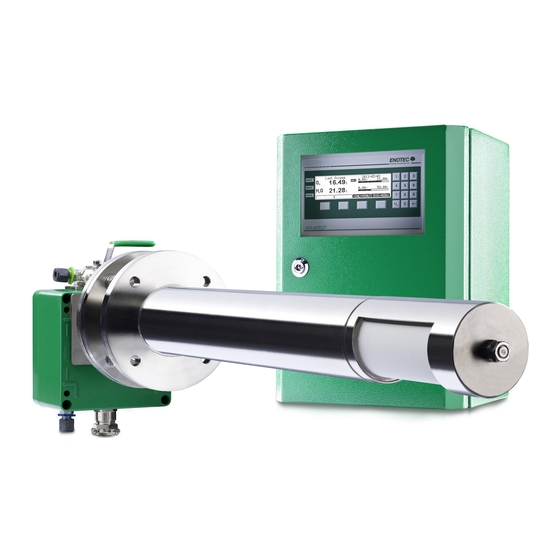
Installation and Operation Manual – AQUATEC 1000 System Description System Overview Figure 1 - AQUATEC 1000 analyzer system with active carbon filter Electronic unit SME5 / IP66 Safe Area - Max. ambient temp.:-20°C to +55°C (-4°F to + 131°F) In-situ measuring probe / Safe Area - Max. - Page 5 System Description Installation and Operation Manual – AQUATEC 1000 Figure 2 - AQUATEC 1000 analyzer system with standard filter Electronic unit SME5 / IP66 Safe Area - Max. ambient temp.:-20°C to +55°C (-4°F to + 131°F) In-situ measuring probe / Safe Area - Max.
-
Page 6: Measuring Principle
Measuring Principle Water Vapor The AQUATEC 1000 does not measure water vapor directly, but calculates it using the measured oxygen content. The water vapor concentration is proportional to the quantity of the displaced oxygen. The formula for water vapor evaluation is represented as follows (see chapter 3.9 for details):... -
Page 7: Disruption Of The Process
(heater, thermocouple and sensor) and reduces their product life. ENOTEC will not accept any responsibility for resultant damage. Storage instructions ENOTEC equipment is to be stored in a dry and ventilated environment. Paint fumes, silicone sprays, etc. must be avoided in the storage environment. Name Plates The name plate contains information about the line voltage, the nominated current, frequency, protection class, year of manufacture, serial number, order number and system order code. -
Page 8: Installation
Installation Installation and Operation Manual – AQUATEC 1000 Installation Warning The system is not equipped with an external power-off switch. The line voltage switch/fuse/breaker must be installed and be in accordance with local technical standards and should be near to the electronic unit and must be clearly marked as such. -
Page 9: Installation Of Probe Signal Cable Fep-0001
Installation Installation and Operation Manual – AQUATEC 1000 Installation of Probe Signal Cable FEP-0001 Abide by the maximum cable length (max. 150m) Note the minimum bending radius. FEP-0001 R = 96 mm +50 °C +90 °C Max. Max. Temp. during installation Temp. -
Page 10: Access To The Terminals
Installation Installation and Operation Manual – AQUATEC 1000 Access to the Terminals Warning Before removing the terminal covers, switch off the mains voltage to the system. Switch the mains voltage on only after attaching the terminal cover. After the installation has been completed, live parts may no longer be accessible. -
Page 11: Wiring Diagram Of The Electronic Unit
Installation Installation and Operation Manual – AQUATEC 1000 Wiring Diagram of the Electronic Unit Figure 7- Wiring diagram of the Electronic Unit Ferrite sleeves (Enclosed) Analogue output cable (customer) Power supply cable (customer) Status signal cable (customer) Probe signal cable... -
Page 12: Aquatec® 1000 Wiring Diagram
Installation Installation and Operation Manual – AQUATEC 1000 AQUATEC® 1000 Wiring diagram Figure 8 - Wiring diagram of the AQUATEC 1000 Analyzer system Doc.-ID: AQUA_16012020_EN... -
Page 13: Installation Of The Probe
For probe lengths exceeding 2000 mm, a support must be mounted inside the duct (every 2m) to prevent the probe and mounting tube from flexing or bending. ENOTEC recommends installing the probe horizontally for the fastest possible response time. -
Page 14: Adjusting The V-Shield / Filter Head
Installation Installation and Operation Manual – AQUATEC 1000 Adjusting the V-shield / filter head Before installing the probe, the direction of flue gas flow must be determined and the filter head assembly turned to such a position that the V-shield faces the oncoming flue gas. The filter head can be turned freely a full 360° for this purpose, by loosening the counter nut, loosening the Allen screw and rotating the filter head / V-shield to the required position, and then tightening the Allen screw and counter nut. -
Page 15: Electrical Connections Of The Probe
Installation Installation and Operation Manual – AQUATEC 1000 2.10 Electrical Connections of the Probe Info The probe cable (FEP-0001) has to be connected to the terminal board in the probe terminal box. Please do not attach the shield to the probe. -
Page 16: Preparation Of The Pneumatic Tube
Installation Installation and Operation Manual – AQUATEC 1000 2.12 Preparation of the pneumatic Cable Pneumatic tubing FEP-0002 Clamp ring Support sleeve Both, the pneumatic tubing for the reference air (blue) and the test gas (green) have to be prepared with... -
Page 17: Pneumatic Connections Of The Probe
Installation Installation and Operation Manual – AQUATEC 1000 2.14 Pneumatic Connections of the Probe Reference air in (FEP-0002: blue tube) Test gas in ( FEP-0002: green tube) Figure 16 - Pneumatic connections of the probe 2.15 Pneumatic Connections of the Electronic Unit... -
Page 18: Initial Operation
Does the voltage specified on the name plate correspond to the line voltage? (See section 1.8 Name Plates) If not, contact ENOTEC. Is the electrical wiring connected correctly? (See section 2.6 AQUATEC 1000 Wiring Diagram) Are the pneumatic connections correct and gas tight? (See sections 2.15 Pneumatic Connections) ... -
Page 19: Keypad And Display
Initial Operation Installation and Operation Manual – AQUATEC 1000 Keypad and Display The controls and display of the AQUATEC 1000 are housed in the electronic unit and are comprised of: Three LED indicators depicting active status reports for limit alarms, maintenance and... -
Page 20: Software Overview And Explanations
Software Overview and Explanations Installation and Operation Manual – AQUATEC 1000 Software Overview and Explanations Menu Overview - SYS-MENU SYS-MENU System Information Actual measured values measured value (% O ) {may be ppm} -mA output 17A/B (mA) sensor input (mV) - Page 21 Software Overview and Explanations Installation and Operation Manual – AQUATEC 1000 Device operating data Powers on counter Hours in operation Min. internal temperature Max. internal temperature Software version and options Software AQUATEC 1000 ~~ Options ~~ ♦ ..System configuration Measuring ranges Meas.range 1 from (% O...
- Page 22 Software Overview and Explanations Installation and Operation Manual – AQUATEC 1000 Calibration settings Time per test gas apply (Min.) Delay time to process (Min.) Measurement value hold on calibration (ON/OFF) Auto.calibration (ON/OFF) ♦ Calibration method (O 1-Point / 2- } visible when set to "ON"...
-
Page 23: Software Explanations - Sys-Menu
Software Overview and Explanations Installation and Operation Manual – AQUATEC 1000 Software Explanations - SYS-MENU 4.2.1 Measuring Ranges (Scaling) The O Measuring range is linearly scaled and converted to a linear current output (0/ 4-20 mA). The parameter „O Measuring range from“... -
Page 24: O 2 Sensor Calibration Values
Software Overview and Explanations Installation and Operation Manual – AQUATEC 1000 4.2.5 Sensor calibration values Info The sensor calibration values can be altered through a 1 or 2 point calibration. Manual entry of values is only necessary after replacing the O sensor. -
Page 25: Bluetooth
The device configuration can also not be altered. Range limits the transmission power of the ENOTEC REMOTE module. Maximum = 100m, medium = 10m, short = 1m. The actual possible range may vary due to structural factors and the reception strength of the Smartphone/Tablet. -
Page 26: Calibration Menu
Software Overview and Explanations Installation and Operation Manual – AQUATEC 1000 Calibration Menu CAL MENU 1 point calibration, O 2 point calibration, O 4.3.1 Calibration Menu - Display Overview The max. adjustable measuring range Trend representation of measured O value... -
Page 27: 1-Point Calibration (Manual)
Software Overview and Explanations Installation and Operation Manual – AQUATEC 1000 Info The oxygen concentration in test air needs not be entered as it is known (20,95 % O During calibration, entry of the test gas concentration value takes place after test gas has been applied. -
Page 28: System Checks
Software Overview and Explanations Installation and Operation Manual – AQUATEC 1000 System Checks Sensor checks Source: Test air sensor .. mV = .. % Flow rate .. l/h Source: Testgas sensor .. mV = .. % Flow rate (3 bar max) .. -
Page 29: Service And Maintenance
Service and Maintenance Installation and Operation Manual – AQUATEC 1000 Service and Maintenance Exchange fuses Warning De-energize the system first! Abb. 27 Position of the fuses fuse system voltage ampere nominal voltage characteristic Size 115 / 230 V AC 0.5 A... -
Page 30: Adjusting Flow Rate (Integrated Pneumatics)
Service and Maintenance Installation and Operation Manual – AQUATEC 1000 Adjusting Flow Rate (integrated Pneumatics) In the instrument air version in the Safe Area housing with an integrated pneumatic unit, it is possible to adjust the reference and test air at the electronic unit. In this respect, the pump and instrument air versions are different: ... -
Page 31: Position Of The Adjustment Valves
Service and Maintenance Installation and Operation Manual – AQUATEC 1000 Position of the adjustment valves Figure 30 - Terminal cover of the SME-53 Electronic Unit showing the position of the reference air and test air valves below Replacing the Filter Warning hot surface The probe may only be removed with heat-insulated gloves. -
Page 32: Cement In New Filter
Figure 32 - Cement new filter in Note The cement dries at room temperature within 24 hours. Using the cement supplied by ENOTEC, all types of ceramic, basalt and sintered metal filters supplied by can be inserted and fixated. Replacing the probe Warning Hot Surface ... -
Page 33: Replacing The O Sensor
Service and Maintenance Installation and Operation Manual – AQUATEC 1000 Replacing the O Sensor Warning Hot Surface The probe may only be removed with heat-insulated gloves. Before removing the probe, always switch off the supply voltage to the electronic system. After removal, store the probe in a safe, protected place and wait until it has cooled down below 35°C/ 95°F. -
Page 34: Exchange Of Probe Inner Parts
Service and Maintenance Installation and Operation Manual – AQUATEC 1000 Protection cap Cell tube Cell Ceramic rod Signal wire Flange gasket Thermocouple Probe tube Heater Screw M5 Figure 34 - Construction of the O sensor holding tube Exchange of Probe Inner Parts Proceed as described in chapter 0 to dismantle the probe inner parts assembly. -
Page 35: Exchange Of Heating Element
Service and Maintenance Installation and Operation Manual – AQUATEC 1000 5.10 Exchange of Heating Element Remove the probe inner part assembly, loosen the clamp, pull out the signal measuring wire and the thermocouple and pull off the heater complete with ceramic support, from the 4-hole ceramic rod. -
Page 36: Relay Outputs / Functions And Correlation
Service and Maintenance Installation and Operation Manual – AQUATEC 1000 5.13 Relay Outputs / Functions and Correlation The relay contacts are designed for 24V and 1A ~, 1A = (Exception: probe valve) Relay Contact Function Terminal System error* Normally closed Signals operation-critical errors... -
Page 37: Digital Inputs
5.17 Extension Modules As an option, the electronic unit is available with several interfaces (RS232, RS485, HART, Fieldbus and ENOTEC REMOTE). If one of these options is ordered you will find a separate manual/specification for the respective interface together with the shipment. -
Page 38: Status Messages
Status Messages Installation and Operation Manual – AQUATEC 1000 Status Messages Error Messages Error Relay signal Description Message contact output 2.00 mA, The error can occur at any time and signalizes a failure of one of the electronic Hardware System error, when not set components. -
Page 39: Alarm Messages
Status Messages Installation and Operation Manual – AQUATEC 1000 Error Messages (cont.) Error Relay signal Description Message contact output The error can only occur during an O sensor calibration. An error reset can be carried sensor System out by the user. A successful re-calibration also resets the error. -
Page 40: Troubleshooting
Troubleshooting Installation and Operation Manual – AQUATEC 1000 Troubleshooting Unsteady, widely varying measuring value (O Possible reasons Procedure Intermittent contact caused by wire breakage Eliminate bad/loose contact Intermittent contact inside the probe - internal mV connection Broken filter element Visual inspection by dismounting the probe... -
Page 41: Technical Data
Technical Data Installation and Operation Manual – AQUATEC 1000 Technical Data Technical Specifications - Electronic Unit Housing: Sheet steel ST37 RAL6029 (SME-57, 19” rack optional) Safe Area Housing: IP66 IP Code: 19“ housing: IP20 Display: LC Dot Matrix 240 x 64... -
Page 42: Technical Specifications - Probe
Technical Data Installation and Operation Manual – AQUATEC 1000 Technical Specifications - Probe Process gas temperature: KES-132x: up to 400°C (with standard ceramic filter) KES-132x: up to 200°C (with active carbon filter) Immersion depth: See dimensional drawings Measuring principle: Zirconium oxide... -
Page 43: Gas Supply - Systems With Instrument Air
Technical Data Installation and Operation Manual – AQUATEC 1000 Gas Supply - Systems with Instrument Air The analyzer system uses the connected instrument air continuously for the supply of reference air, and during calibration and system test respectively, for the supply of test air (test gas 1). -
Page 44: Dimensional Drawings
Dimensional drawings Installation and Operation Manual – AQUATEC 1000 Dimensional drawings Dimensions of Electronic Unit Housing versions Figure 36 - Dimensions in mm of the SME-53 Probe Dimensions Figure 37 - Dimensions of the KES-132X probes Doc.-ID: AQUA_16012020_EN... -
Page 45: Counter Flange Dimensions
Dimensional drawings Installation and Operation Manual – AQUATEC 1000 Figure 39 – Dimensions in mm of the KES-132X probes with KES-1320600AK (active carbon filter) Counter Flange Dimensions Figure 38 - Dimensions of counter flange for KES 132X Doc.-ID: AQUA_16012020_EN... -
Page 46: Dimensions Of Protection Tube Flanges
Dimensional drawings Installation and Operation Manual – AQUATEC 1000 Dimensions of protection tube flanges Figure 39 - Dimensions of protection tube flanges Doc.-ID: AQUA_16012020_EN... -
Page 47: Spare Parts
Spare Parts Installation and Operation Manual – AQUATEC 1000 Spare Parts Probe Components - KES-132X Figure 40 - KES-132X Probe Components Part Part No. Connection Box ASK-1001 Measuring probe tube MSR-132X Probe flange gasket FLD-132X Probe inner part SIK-132X Oxygen measuring cell... -
Page 48: Probe Inner Parts Assembly
Spare Parts Installation and Operation Manual – AQUATEC 1000 Probe inner parts assembly Figure 41 - Probe inner parts assembly (KES-1321-2) Figure 42 - Reinforced probe inner part assembly (KES/KIS-1323) Article Number (depends on probe type) Description KES-1321-2 KES-1323 /... -
Page 49: Mounting Plates Of The Electronic Unit
Spare Parts Installation and Operation Manual – AQUATEC 1000 Mounting Plates of the Electronic Unit Parts List Test gas and reference air unit with internal TRA-0017 Transformer prim. 2*115V, sec. 115V PLU-0028 Test air pump for SME5 720 l/h Test gas solenoid valve P01 for... -
Page 50: Display Board
Spare Parts Installation and Operation Manual – AQUATEC 1000 Parts List Mounting plate 2 0-L-000047 Optional mA-output board. 0-L-000180 SME5 power board Filter for reference air and test air - PLF-0003 for version with internal pumps Figure 45 - Mounting plate 2... -
Page 51: Warranty
E N O T E C W A R R A N T Y ENOTEC warrants that systems manufactured and sold by it will, upon shipment, be free of defects in workmanship or material. Should any failure to conform to this warranty become apparent during the relevant warranty periods, ENOTEC shall, upon prompt written notice from the purchaser, correct such nonconformity by repair or replacement of the defective part or parts. -
Page 52: Declaration Of Conformity
Declaration of Conformity Installation and Operation Manual – AQUATEC 1000 Declaration of Conformity We hereby declare that the products listed below, based on their conception and design as well as in the equivalent execution which we have brought into circulation, comply with the essential safety and health requirements of the EC-directives as follows. -
Page 53: Index
Index Installation and Operation Manual – AQUATEC 1000 Index P Access to the Terminals ........... 10 Pneumatic Connections Adjusting the Flow Rate ........... 30 Probe ................17 Adjusting the V-shield ............14 Position of the adjustment valves ........31 AQUATEC 1000 Wiring diagram ........12 Pressure and Flow rates ..........
Need help?
Do you have a question about the AQUATEC 1000 and is the answer not in the manual?
Questions and answers