
Related Manuals for Enotec OXITEC 5000 Series


Summary of Contents for Enotec OXITEC 5000 Series
- Page 1 Installation and Operation Manual Analyzer System ® ® OXITEC 5000 / OXITEC 5000+ Version 33 for Software Version: 4.13 Doc.-ID: OXI-11022020-EN...
- Page 2 ENOTEC. This leads to a considerably increased service life compared to "glued or cemented" sensors that have a tendency to leak or crack during operation. All ENOTEC instruments are thoroughly tested in the factory and are subject to a strict ISO 9001 and internal quality assurance ®...
-
Page 3: Table Of Contents
Automatic Calibration (ACAL) ......24 Warranty 4.2.9 Automatic Calibration Settings ......24 4.2.10 ENOTEC REMOTE ........... 25 Declaration of Conformity 4.2.11 Measuring units ..........25 Index 4.2.12 ... -
Page 4: System Description
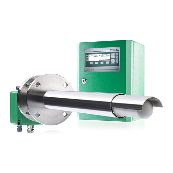
System Description ® Installation and Operation Manual OXITEC 5000 System Description System overview Info Depending on the system configuration ordered by the customer, the electronic unit and / or probe may vary. Refer to chapters B and B.2 for different versions of electronic units and probes. ®... - Page 5 System Description ® Installation and Operation Manual OXITEC 5000 ® Figure 2 - OXITEC 5000 (probe with cooling tube for flue gas temperatures of up to 1600°C) Safe Area - max. ambient temperature: Electronic unit SME-5 / IP66 -20 °C to +55 °C (-4 °F to +131 °F) Safe Area - max.
-
Page 6: Measuring Principle
Storage instructions ENOTEC equipment and spares are to be stored in a dry and ventilated environment at temperatures between -40 °C to +80 °C (-40 °F to 176 °F). Paint fumes, silicone sprays, etc. must be avoided in the storage environment. -
Page 7: Name Plates
System Description ® Installation and Operation Manual OXITEC 5000 Name plates The name plate contains information about the line voltage, the nominated current, frequency, protection class, year of manufacture, serial number, order number and system order code. The system order code refers to information which is detailed in the system test report and supplied with the system. SME-53 Electronic Unit Probe... -
Page 8: Installation
Installation ® Installation and Operation Manual OXITEC 5000 Installation Warning The system is not equipped with an external power-off switch. The line voltage switch/fuse/breaker must be installed and be in accordance with local technical standards and should be near to the electronic unit and must be clearly marked as such. -
Page 9: Installation Of Probe Signal Cable Fep-0001
Installation ® Installation and Operation Manual OXITEC 5000 Installation of probe signal cable FEP-0001 Abide by the maximum cable length (max. 150m) Note the minimum bending radius. FEP-0001 R = 96 mm +50 °C +90 °C Max. Max. Temperature during Temperature during operation -5 °C -40 °C... -
Page 10: Access To The Terminals
Installation ® Installation and Operation Manual OXITEC 5000 Access to the terminals Warning Before removing the terminal covers, switch off the mains voltage to the system. Switch the mains voltage on only after attaching the terminal cover. After the installation has been completed, live parts may no longer be accessible. -
Page 11: Wiring Diagram Of The Electronic Unit
Installation ® Installation and Operation Manual OXITEC 5000 Wiring diagram of the electronic unit Figure 7 - Wiring diagram of the Electronic Unit Ferrite sleeves (enclosed) Analogue output cable (customer) Power supply cable (customer) Status signal cable (customer) Probe signal cable Pressure transmitter analogue input cable (optional, customer) Power supply... -
Page 12: Oxitec® 5000 Wiring Diagram
Installation ® Installation and Operation Manual OXITEC 5000 OXITEC® 5000 Wiring diagram Figure 8 - Wiring diagram of the OXITEC 5000 Analyzer system Doc.-ID: OXI-11022020-EN... -
Page 13: Installation Of The Probe
For probe lengths exceeding 2000 mm, a support must be mounted inside the duct (every 2 m) to prevent the probe and mounting tube from flexing or bending. ENOTEC recommends installing the probe horizontally (- 1 ° to - 3 °) for the fastest possible response time. -
Page 14: Mounting Of The Probe
Installation ® Installation and Operation Manual OXITEC 5000 Mounting of the probe Figure 9 - Mounting of the O probe – for dimensions, see section B Counter flange which has been welded gas tight at correct Probe connection box angle to duct Flange gasket Duct wall Protection tube... -
Page 15: Mounting A Probe With Cooling Protection Tube
Installation ® Installation and Operation Manual OXITEC 5000 Mounting a probe with cooling protection tube Info If a cooling tube is used, the part of the protection tube projecting from the duct wall must be insulated or heated if necessary, to prevent its temperature from dropping below the dew point. Make sure that the gas outlet is not blocked. -
Page 16: Electrical Connections Of The Probe
Installation ® Installation and Operation Manual OXITEC 5000 2.11 Electrical connections of the probe Info The shield of the probe cable must only be connected at the electronic housing at the PE terminal. Under no circumstance should the shield also be connected at the probe. 1: - mV O2 sensor (white-brown) 2: + mV O2 sensor (brown) 3: + mV thermocouple 1 (green) -
Page 17: Preparation Of The Pneumatic Cable
Installation ® Installation and Operation Manual OXITEC 5000 2.13 Preparation of the pneumatic cable Pneumatic cable FEP-0002 Clamp ring Support sleeve Both, the pneumatic tubing for the reference air (blue) and the test gas (green) have to be prepared with support sleeves , clamp rings and nuts... -
Page 18: Pneumatic Connections Of The Probe
Installation ® Installation and Operation Manual OXITEC 5000 Electronics with external pneumatics - SME-50000080 Choke non return valve A - Reference air B - Test air Solenoid valve 3/2 ways Flow meter Instrument air in Test air in Test gas in Test gas out Reference air out Figure 15 - SME-50000080 gas plan for external pneumatics. -
Page 19: Pneumatic Connections Of Electronic Unit
Installation ® Installation and Operation Manual OXITEC 5000 2.16 Pneumatic connections of electronic Unit Tube Pump version Instrument air version 1/4“ Testgas in Testgas in 1/4“ Testgas out Testgas out 1/4“ Reference air in Instrument air in 1/4“ Reference air out Reference air out 1/4“... -
Page 20: Initial Operation
Switch on the line voltage to the system. After a short power up information, the user is prompted to Select language, set the System date, System time, enter a TAG number and ENOTEC REMOTE code (only if option ENOTEC REMOTE is factory activated). -
Page 21: Display - Measuring Mode
Initial Operation ® Installation and Operation Manual OXITEC 5000 Display - measuring mode TAG number Measured value Active measuring range Blinking indicators showing under or over measuring range Last access Measured component Limit alarm indicators min-Alarm / max-Alarm * Only if the O2 limit alarms are switched on and the limits are Softkey titles within the set measuring range. -
Page 22: Software Overview And Explanations
Software Overview and Explanations ® Installation and Operation Manual OXITEC 5000 Software Overview and Explanations Menu overview - SYS-MENU SYS-MENU System Information Actual measured values measured value (% O ) {may be ppm} -mA output 17A/B (mA) sensor input (mV) Flow rate reference air (l/h) probe temperature (°C / °F) probe heater power (%) - Page 23 Software Overview and Explanations ® Installation and Operation Manual OXITEC 5000 Software version and options Software OXITEC 5000 ~~ Options ~~ ♦ ..SYS-MENU System configuration Measuring ranges Meas.range 1 from (% O , ppm O Meas.range 1 to (% O , ppm O Meas.range 2 from (% O , ppm O...
- Page 24 Location altitude (m) System clock/TAG number System date (jjjj-mm-tt) System time (hh:mm:ss) ENOTEC REMOTE settings (optional) } Visible when ENOTEC REMOTE interface is activated ENOTEC REMOTE (ON/OFF) ENOTEC REMOTE code (8 digit code) } Visible when ENOTEC REMOTE is ON...
-
Page 25: Software Explanations - Sys-Menu
Software Overview and Explanations ® Installation and Operation Manual OXITEC 5000 Software Explanations - SYS-MENU 4.2.1 Measuring ranges (Scaling) The O measuring range is linearly scaled and converted to a linear current output (0/ 4-20 mA). The parameter „O measuring range from“ is the start value the O range, leading to an analogue output of 4,00 mA. -
Page 26: O 2 Sensor Calibration Values
Software Overview and Explanations ® Installation and Operation Manual OXITEC 5000 4.2.5 Sensor calibration values Info The sensor calibration values can be altered through a 1 or 2 point calibration. Manual entry of values is only necessary after replacing the O sensor.(The sensor calibration values, "cell constant"... -
Page 27: Enotec Remote
Figure 25 - ENOTEC REMOTE connection active Info A maximum of 16 users (smartphones /tablets) can connect to the ENOTEC REMOTE module of an ENOTEC analyzer. Should additional users attempt a connection, the connection will fail. In this case, manually switch off the ENOTEC REMOTE and switch it back on again SYS MENU =>... -
Page 28: Service (Factory Service Settings)
Software Overview and Explanations ® Installation and Operation Manual OXITEC 5000 4.2.15 Service (factory service settings) The service functions are password protected and are only accessible by trained service personnel. These functions are protected with a code, different to the system code. Calibration menu CAL MENU 1 point calibration, O... -
Page 29: 1-Point Calibration (Manual)
Software Overview and Explanations ® Installation and Operation Manual OXITEC 5000 4.3.2 1-point calibration (manual) During the 1-point calibration of the sensor, the calibration offset is determined. Test air is hereby applied to the sensor. In systems without an integrated pneumatic unit, test gas needs to be applied manually and the flow control also may need to be checked and adjusted if necessary. -
Page 30: System Checks
Software Overview and Explanations ® Installation and Operation Manual OXITEC 5000 System checks Sensor checks Source: Test air sensor .. mV = .. % Flow rate .. l/h Source: Test gas sensor .. mV = .. % Flow rate (3 bar max) .. -
Page 31: Service And Maintenance
Service and Maintenance ® Installation and Operation Manual OXITEC 5000 Service and Maintenance Exchange fuses Warning De-energize the system first! Abb. 27 Position of the fuses fuse system voltage ampere nominal voltage characteristic Size 115 / 230 V AC 0.5 A 250 V AC T / L 5x20 mm... -
Page 32: Adjusting Flow Rate (Integrated Pneumatics)
Service and Maintenance ® Installation and Operation Manual OXITEC 5000 Adjusting Flow Rate (integrated Pneumatics) In the instrument air version in the Safe Area housing with an integrated pneumatic unit, it is possible to adjust the reference and test air at the electronic unit. In this respect, the pump and instrument air versions are different: ... -
Page 33: Position Of The Adjustment Valves
Service and Maintenance ® Installation and Operation Manual OXITEC 5000 Position of the adjustment valves Figure 30 - Terminal cover of the SME-53 electronic unit showing the position of the reference air and test air valves below. Adjusting Flow Rate (SME-54) With systems in 19“... -
Page 34: Replacing The Filter
Figure 33 - Cement new filter in Note The cement dries at room temperature within 24 hours. Using the cement supplied by ENOTEC, all types of ceramic, basalt and sintered metal filters supplied by can be inserted and fixated. Doc.-ID: OXI-11022020-EN... -
Page 35: Replacing The Probe
Service and Maintenance ® Installation and Operation Manual OXITEC 5000 Replacing the probe Warning Hot Surface The probe may only be removed with heat-insulated gloves. Before removing the probe, always switch off the supply voltage to the electronic system. Disconnect the wires at the probe connection box. - Page 36 Service and Maintenance ® Installation and Operation Manual OXITEC 5000 Clean the flange at the probe tube with fine sandpaper. Tighten the new measuring cell with a new metal gasket sealing and four new screws at the measuring cell flange of the probe tube. Insert the probe inner parts and ensure that the inner parts do not bind in the probe tube.
-
Page 37: Exchange Of Probe Inner Parts
Service and Maintenance ® Installation and Operation Manual OXITEC 5000 Exchange of Probe Inner Parts Proceed as described in chapter 5.8 to dismantle the probe inner parts assembly. The exchange of the thermocouple element is an exception, because this can be changed without dismounting the probe inner part as a whole. -
Page 38: Relay Outputs / Functions And Correlation
Service and Maintenance ® Installation and Operation Manual OXITEC 5000 5.10 Relay Outputs / Functions and Correlation The relay contacts are designed for 24V and 1A ~, 1A = (Exception: probe valve) Relay Contact Function Terminal System error* Normally closed Signals operation-critical errors X5 (19A/B) Maintenance Normally open... -
Page 39: Digital Inputs
Service and Maintenance ® Installation and Operation Manual OXITEC 5000 5.11 Digital Inputs The digital inputs are designed for a direct voltage of 12 V - 24 V DC for logical “High”. Logical “Low” corresponds to a voltage less than 1 V. Digital input Function Calibration release... -
Page 40: Status Messages
Status Messages ® Installation and Operation Manual OXITEC 5000 Status Messages Error Messages Error Relay signal Description Message contact output System 2.00 mA, The error can occur at any time and signalizes a failure of one of the Hardware error, when not set electronic components. -
Page 41: Alarm Messages
Status Messages ® Installation and Operation Manual OXITEC 5000 Error Messages (cont.) Error Relay signal Description Message contact output The error can only occur during an O sensor calibration. An error reset can sensor System be carried out by the user. A successful re-calibration also resets the error. offset too error, open Possible causes: defective false test gas (not applicable with test air), test... -
Page 42: Maintenance Messages
Status Messages ® Installation and Operation Manual OXITEC 5000 Maintenance Messages Maintenance Relay Description message contact Measured value(s) Maint. When measured values held is set to on, the determined O -mA output remains held closed saved for a duration before a calibration. Doc.-ID: OXI-11022020-EN... -
Page 43: Troubleshooting
Troubleshooting ® Installation and Operation Manual OXITEC 5000 Troubleshooting Unsteady, widely varying measuring value (O Possible reasons Procedure Intermittent contact caused by wire breakage Eliminate bad/loose contact Intermittent contact inside the probe - internal mV connection Broken filter element Wrongly installed V-shield Visual inspection by dismounting the probe Probe has been installed without filter head display remains at the end of the measuring range or is higher than expected... -
Page 44: Technical Data
Technical Data ® Installation and Operation Manual OXITEC 5000 Technical Data Technical Specifications - Electronic Unit Housing: sheet steel powder coated; RAL6029 (GRP version optional) (SME-54, 19” rack optional) Safe Area Housing: IP66 IP Code: GRP cabinet: IP66 19“ housing: IP20 Display: LC Dot Matrix 240 x 64 - LED backlit... -
Page 45: Technical Specifications - Probe
Technical Data ® Installation and Operation Manual OXITEC 5000 Technical Specifications - Probe KES-132x: up to 400°C ( 752 °F) Process gas temperature: KES-200x: up to 600°C (1112 °F) KIS-200x: up to 800°C (1472 °F) KES-500x: up to 600°C (1112 °F) up to 1600°C (2912 °F) with cooling tube Insertion depth: KES-1321:... -
Page 46: Gas Supply - Systems With Instrument Air
Technical Data ® Installation and Operation Manual OXITEC 5000 Gas Supply - Systems with Instrument Air The analyzer system uses the connected instrument air continuously for the supply of reference air, and during calibration and system test respectively, for the supply of test air (test gas 1). Instrument air supply for reference air / test air Specification: According to ISO 8573-1 class 2... -
Page 47: Dimensional Drawings
Dimensional drawings ® Installation and Operation Manual OXITEC 5000 Dimensional drawings Dimensions of Electronic Unit Housing versions Figure 38 – Dimensions in mm of the SME-53 Figure 39 - Dimensions in mm of the SME-54 Figure 40 - GRP protective housing (optional) - Dimensions in mm Doc.-ID: OXI-11022020-EN... -
Page 48: Probe Dimensions
Dimensional drawings ® Installation and Operation Manual OXITEC 5000 Probe Dimensions Figure 41 - Dimensions of the KES-132X probes Figure 42 – Dimensions in mm of the KES-132X probes with cooling protection tube Doc.-ID: OXI-11022020-EN... - Page 49 Dimensional drawings ® Installation and Operation Manual OXITEC 5000 Figure 43 - Dimensions of the KES-200X probes Figure 44 - Dimensions in mm of the KES-200X probes with cooling protection tube Doc.-ID: OXI-11022020-EN...
- Page 50 Dimensional drawings ® Installation and Operation Manual OXITEC 5000 Figure 45 - Dimensions in mm of the KES-500X probes Figure 46 - Dimensions of the KES-500X probes with cooling protection tube Doc.-ID: OXI-11022020-EN...
-
Page 51: Counter Flange Dimensions
Dimensional drawings ® Installation and Operation Manual OXITEC 5000 Counter Flange Dimensions Figure 47 - Dimensions of counter flange ASR-1320 for KES 132X Figure 48 - Dimensions of counter flange ADP-2000 Doc.-ID: OXI-11022020-EN... - Page 52 Dimensional drawings ® Installation and Operation Manual OXITEC 5000 Figure 49 - Dimensions of counter flange ADP-2000-S02 Doc.-ID: OXI-11022020-EN...
-
Page 53: Dimensions Of Protection Tube Flanges
Dimensional drawings ® Installation and Operation Manual OXITEC 5000 Dimensions of protection tube flanges Figure 50 - Dimensions of protection tube flanges Doc.-ID: OXI-11022020-EN... -
Page 54: Spare Parts
Spare Parts ® Installation and Operation Manual OXITEC 5000 Spare Parts Probe Components - KES-132X Figure 51 - KES-132X Probe Components Part Part No. Connection Box ASK-1001 Measuring probe tube MSR-132X Probe flange gasket FLD-132X Probe inner part SIK-132X Oxygen sensor ZO2-00(0/1)1 Measuring sensor gasket MZD-0001... -
Page 55: Probe Components - Kes-200X
Spare Parts ® Installation and Operation Manual OXITEC 5000 Probe Components - KES-200X Figure 52 - KES-200X Probe Components Part Part No. Connection Box ASK-1001 Measuring probe tube MSR-200X Probe flange gasket FLD-200X Spacer 0-R-000476 Probe inner part SIK-200X Oxygen measuring cell ZO2-00(0/1)1 Measuring cell gasket MZD-0001... -
Page 56: Probe Components - Kes-500X
Spare Parts ® Installation and Operation Manual OXITEC 5000 Probe Components - KES-500X Figure 53 - KES-500X Probe Components Part Part No. Connection Box ASK-1001 Measuring probe tube MSR-200X Probe flange gasket FLD-200X Probe inner part SIK-200X Oxygen sensor cell ZO2-00(0/1)1 Measuring sensor gasket MZD-0001... -
Page 57: Probe Inner Parts Assembly
Spare Parts ® Installation and Operation Manual OXITEC 5000 Probe inner parts assembly Figure 54 - Probe inner parts assembly Figure 55 – Reinforced probe inner part assembly (KES/KIS-1323/200x/500x) Article Number (depends on probe type) Description KES-1323 / KES-1321-2 KES-200X / KES-500X KES-2001 Heater support tube HZH-00002... -
Page 58: Mounting Plates Of The Electronic Unit
Spare Parts ® Installation and Operation Manual OXITEC 5000 Mounting Plates of the Electronic Unit Parts List Test gas and reference air unit with internal pumps Transformer prim. 2*115V, TRA-0017 sec. 115V PLU-0028 Test air pump for SME5 720 l/h Test gas solenoid valve P01 for PGM-0001 SME-53 - with pneumatic unit... -
Page 59: Display Board
Spare Parts ® Installation and Operation Manual OXITEC 5000 Parts List Mounting plate 2 0-L-000047 Optional mA-output board. 0-L-000180 SME5 power board Filter for reference air and test air PLF-0003 - for version with internal pumps Figure 58 - Mounting plate 2 Figure 59 - Mounting plate 2 Display Board Parts List... -
Page 60: Warranty
E N O T E C W A R R A N T Y ENOTEC warrants that systems manufactured and sold by it will, upon shipment, be free of defects in workmanship or material. Should any failure to conform to this warranty become apparent during the relevant warranty periods, ENOTEC shall, upon prompt written notice from the purchaser, correct such nonconformity by repair or replacement of the defective part or parts. -
Page 61: Declaration Of Conformity
EC-directives as follows. Any unauthorized changes to the products, renders this declaration invalid. The manufacturer carries the sole responsibility for issuing this declaration. Manufacturer: ENOTEC GmbH Höher Birken 6 51709 Marienheide - Germany Tel.: +49 2264 45 78-0... -
Page 62: Index
Index ® Installation and Operation Manual OXITEC 5000 Index N Access to the Terminals ........8 Name Plate ............5 Adjusting the Flow Rate ........30 Name Plates ............5 Adjusting the V-shield ........13 O C OXITEC® 5000 Wiring diagram ...... 10 Calibration ............
Need help?
Do you have a question about the OXITEC 5000 Series and is the answer not in the manual?
Questions and answers