
Related Manuals for Enotec OXITEC ECONOMY


Summary of Contents for Enotec OXITEC ECONOMY
- Page 1 Installation and Operation Manual O2 Analyzer System OXITEC ECONOMY ® Version 1.10 for Software Version: 4.09 Doc.-ID: ECO-12022015-EN...
- Page 2 ENOTEC. This technique results in a considerable increase in service life compared to „glued or cemented“ measuring cells of ENOTEC competitors, which have a tendency to leak or crack during operation. The OXITEC sensor has a proven gas- tight design, providing greater measuring accuracy, durability and longer working life time.
-
Page 3: Table Of Contents
Table of Contents Installation and Operation Manual – OXITEC Economy Table of Contents System Description Service and Maintenance System Overview ..........2 Test Gas Tubing (Customer supply) ....22 Intended Use of OXITEC ECONOMY ....3 ... -
Page 4: System Description
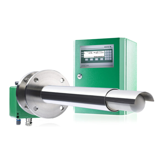
Installation and Operation Manual – OXITEC Economy System Description System Overview - OXITEC Economy System (for flue gas temperatures of up to 400°C) Figure Figure 2 - OXITEC Economy System (with cooling protection tube for flue gas temperatures of up to 1400°C) Doc.-ID: ECO-12022015-EN... -
Page 5: Intended Use Of Oxitec Economy
ENOTEC will not accept any responsibility for resultant damage. Storage instructions ENOTEC equipment and spares are to be stored in a dry and ventilated environment with temperatures between 5°C and 35°C. Paint fumes, silicone sprays, etc. must be avoided in the storage environment. -
Page 6: Installation
Installation Installation and Operation Manual – OXITEC Economy Installation Warning The device must be provided with an external power-off switch. The line voltage switch/fuse/breaker must be in accordance with the local technical standards and should be near to the electronic unit and must be clearly marked as such. -
Page 7: Access To The Terminals
Installation Installation and Operation Manual – OXITEC Economy 2.1.1 Access to the Terminals Figure 6 - Access to the terminals Installation of Probe Signal Cable Abide by the maximum cable length (max. 150m) Cross the probe signal cable (FEP-0001) at right angle to power supply cables. -
Page 8: Installation Of The Probe
Installation Installation and Operation Manual – OXITEC Economy Probe Cable FEP-0001 Function Diameter Colours Additional info. Measuring cell 2 x 0,75 mm white-brown / brown With shield Thermocouple 2 x 0,75 mm green / white With shield black / blue / green-... -
Page 9: Install O Probe
Installation Installation and Operation Manual – OXITEC Economy Install O Probe 2.4.1 Welding of the Counter Flange Caution The counter flange must be welded gas tight to the duct wall at the required angle. Make sure that the combustion process is not in operation and the temperature of the flue gas duct at the mounting place allows work without any risk of burns. -
Page 10: Installation Of The O2 Probe
Installation Installation and Operation Manual – OXITEC Economy 2.4.3 Installation of the O2 Probe Caution For probe installation into the duct flange use only new and undamaged gaskets Tighten the flange nuts correctly to get a gas tight flange connection. Insulate the duct flange to prevent against dew point corrosion problems. -
Page 11: Electrical Connections Of The Electronic Unit
Installation Installation and Operation Manual – OXITEC Economy Electrical Connections of the Electronic Unit Figure 12 - Electrical connections of the electronic unit Ferrite sleeves (ENOTEC supply) Analogue output cable (Customer) Line voltage supply cable (Customer) Digital output cable (Customer) -
Page 12: Electrical Wiring Diagram
Installation Installation and Operation Manual – OXITEC Economy Electrical Wiring Diagram Figure 13 - Electrical wiring diagram Doc.-ID: ECO-12022015-EN... -
Page 13: Relay Contacts, Functions
Installation Installation and Operation Manual – OXITEC Economy 2.6.1 Relay Contacts, Functions Relay Contact for Contact closed Contact open System fault No System fault System fault has occurred (error code on display) Maintenance System switched off or Maintenance No maintenance... -
Page 14: Initial Operation
Switch on the line voltage to the system. After a short power up information, the user is prompted to Select language, set the System date, System time, enter a TAG number and ENOTEC REMOTE code (only if option ENOTEC REMOTE is factory activated). -
Page 15: Display - Measuring Mode
Initial operation Installation and Operation Manual – OXITEC Economy Display - Measuring Mode TAG number Measured value Blinking indicators showing under or over measuring range Last access Measured component Softkey titles Figure 17 - Measuring mode Keypad and Display The controls and display of the COMTEC®... -
Page 16: Software Overview And Explanations
Software Overview and Explanations Installation and Operation Manual – OXITEC Economy Software Overview and Explanations Software Overview - SYS-MENU SYS-MENU System Information Actual measured values measured value (% O -mA output 17A/B (mA) sensor input (mV) probe temperature (°C / °F) - Page 17 Software Overview and Explanations Installation and Operation Manual – OXITEC Economy ♦ ..SYS-MENU System configuration Measuring ranges Meas.range from (% O Meas.range to (% O mA output type (0-20 mA / 4-20 mA) mA output on system error (mA) sensor calibration values cal.value - offset (mV)
-
Page 18: Software Explanations - Sys-Menu
Software Overview and Explanations Installation and Operation Manual – OXITEC Economy Software Explanations - SYS-MENU 4.2.1 Measuring Ranges (Scaling) The O Measuring range is linearly scaled and converted to a linear current output (0/ 4-20 mA). The parameter „O Measuring range from“... -
Page 19: O 2 Sensor Calibration Values
The device configuration can also not be altered. Range limits the transmission power of the ENOTEC REMOTE module. Maximum = 100m, medium = 10m, short = 1m. The actual possible range may vary due to structural factors and the reception strength of the strength of the Smartphone/Tablet. -
Page 20: Measuring Units
Software Overview and Explanations Installation and Operation Manual – OXITEC Economy 4.2.8 Measuring units Measuring units can be set for temperature (°C / °F). 4.2.9 Language Set the language for all text shown on the display. One can choose between English, German, Spanish and Polish. -
Page 21: Cal Menu
Software Overview and Explanations Installation and Operation Manual – OXITEC Economy CAL MENU CAL MENÜ 1 point calibration, O 2 point calibration, O 4.3.1 Check Test air / Test gas settings Check and confirm test air/ test gas flow rate... -
Page 22: 1-Point Calibration (Manual)
Software Overview and Explanations Installation and Operation Manual – OXITEC Economy Info The oxygen concentration in test air needs not be entered as it is known (20, 95 % O During calibration, entry of the test gas concentration value takes place after test gas has been applied. -
Page 23: System Check
Software Overview and Explanations Installation and Operation Manual – OXITEC Economy System Check Sensor check Source: Testair sensor .. mV = .. % Flow rate .. l/h Source: Testgas sensor .. mV = .. % Flow rate (3 bar max) .. -
Page 24: Service And Maintenance
Service and Maintenance Installation and Operation Manual – OXITEC Economy Service and Maintenance Test Gas Tubing (Customer supply) 5.1.1 ... preparation Preparation of the test gas tubing prior to the connection to the O Probe: Test gas tubing (customer) ¼'' or 6/4mm outside/internal... -
Page 25: With Test Gas Bottle
Service and Maintenance Installation and Operation Manual – OXITEC Economy 5.2.2 …with Test Gas Bottle Test Gas “Air“ Specification: 20,95 Vol.% O ± 2% rel. in N (Factory recommendation) alternative: Instrument Air as follows: Particle Size: max. Oil Content: max. -
Page 26: Exchange The O Probe Filter Head
Service and Maintenance Installation and Operation Manual – OXITEC Economy Exchange the O Probe Filter Head 5.5.1 Remove the Filter Head Counter nut M8 loosen Allen key screw M8 loosen Remove filter head from the O probe Figure 29 - Removing the filter head 5.5.2... -
Page 27: Status Messages
Contact one of the ENOTEC service error 1-7 open differently points, if the error returns after restarting the system. -
Page 28: Alarm Messages
Indicates a hardware error of the ENOTEC REMOTE module. Possible cause: error, REMOTE the ENOTEC REMOTE module is defective. open module Unlisted errors: Other errors cannot be remedied by the customer. Please contact an ENOTEC service point Alarm Messages Relay Error Message Description contact... -
Page 29: Technical Data
® Technical Data Installation and Operation Manual - OXITEC Technical Data Technical Specifications - Electronic Unit Sheet steel ST37 powder coated Housing: RAL6029 IP66 IP Code: LC Dot Matrix 240 x 64 Display: LED backlit Membrane keypad Keypad: alarm -orange, maintenance - orange, error -red Signal LEDs: 2 x 0,00 to 25,00 Vol.% O measuring range:... -
Page 30: Technical Specifications - Probe
Technical Data ® Installation and Operation Manual - OXITEC Technical Specifications - Probe max. 400°C/752°F Process gas temperature Up to 1400°C/2552°F with cooling protection tube Up to 500 mm Immersion depth: Up to 1000 mm Immersion depth with cooling tube: Zirconium oxide Measuring principle: -50 to +50mbar (-0.725 to +0.725 PSIG) -
Page 31: Dimensional Drawings
Info All dimensions are in mm (metric system). Probes ENOTEC Article No.: Probe with filter head for clean flue gas: ECO-00001000 Figure 32 - Low Dust Probe (max. 400°C) ENOTEC Article No.: Probe with filter head for high dust: ECO-000011(21)00 Figure 33 - High Dust Probe (max. -
Page 32: Counter Flanges (Optional)
Dimensional Drawings ® Installation and Operation Manual - OXITEC Counter Flanges (Optional) Figure 35 - Dimensions of counter flange ADP-1000 Figure 36 - Dimensions of counter flange ADP-1000 Doc.-ID: ECO-12022015-EN... -
Page 33: Dimensions Of Electronic Unit
® Dimensional Drawings Installation and Operation Manual - OXITEC Dimensions of Electronic Unit Figure 37 - Dimensions of electronic unit Doc.-ID: ECO-12022015-EN... -
Page 34: Spare Parts
Spare Parts ® Installation and Operation Manual - OXITEC Spare Parts Probe without Filter Head ENOTEC Article No.: Part description KES-10000000 Probe without Filter Head with Flange Gasket Probe Flange Gasket FLD-1000 Figure 38 - O probe Probe Components Figure 39 - O probe components Doc.-ID: ECO-12022015-EN... -
Page 35: Components Of The Cooling Tube
® Spare Parts Installation and Operation Manual - OXITEC Components of the Cooling Tube Figure 40 - Cooling tube components ENOTEC Article No. Description ECO-KSR00001 Cooling Tube with immersion depth 500mm ECO-KSR00002 Cooling Tube with immersion depth 1000mm ® PRZ-045-0500... - Page 36 Spare Parts ® Installation and Operation Manual - OXITEC Electronic Unit (continued) Figure 42 - Electronic unit components ENOTEC Article No. Description ® 0-A-000159 OXITEC 5000 ECONOMY housing (with Lower Mounting Plate Upper Mounting Plate Cover Front plate Cover Terminals...
-
Page 37: Probe Cable With Plug
® Spare Parts Installation and Operation Manual - OXITEC Probe Cable with Plug No. ENOTEC Article No. Description BG-ASK-0002 Probe Connection Plug with socket insert and screw FEP-0001 Probe Cable Figure 43 - Probe Cable with Plug Doc.-ID: ECO-12022015-EN... -
Page 38: System Options
Figure 44 - O Limit alarms ENOTEC Article No.: ECO-00200000 Duct Flange The duct flange is required for the probe installation at the flue duct. The duct flange has to be welded gas tight to the flue duct by the customer. -
Page 39: Ec Declaration Of Conformity
® EC Declaration of Conformity Installation and Operation Manual - OXITEC EC Declaration of Conformity Manufacturer: ENOTEC GmbH Höher Birken 6 D-51709 Marienheide EC Declaration of Conformity ® We hereby declare that the product OXITEC oxygen analyzer system, based on its conception and design as well as in the equivalent execution which we have brought into circulation, complies to the EC-directives as follows. -
Page 40: Warranty
E N O T E C W A R R A N T Y ENOTEC warrants that systems manufactured and sold by it will, upon shipment, be free of defects in workmanship or material. Should any failure to conform to this warranty become apparent during the relevant warranty periods, ENOTEC shall, upon prompt written notice from the purchaser, correct such nonconformity by repair or replacement of the defective part or parts. -
Page 41: Index
® Index Installation and Operation Manual OXITEC Index Bottle Test Gas Supply ..........23 Test Gas Supply to the O2 Probe ......22 A Test Gas Tubing ............22 Access to the Terminals ............. 5 Menu Explanations Delay time to process ..........17 C ... - Page 42 ++49 (0) 2264 / 45 78 – 0 Fax: ++49 (0) 2264 / 45 78 – 30 E-Mail: info@enotec.de Internet: www.enotec.com ENOTEC Sales and Service Sales North Sales West Telefon: +49 (0) 4171 6672 70 Telefon: +49 (0) 2264 4578 25...
Need help?
Do you have a question about the OXITEC ECONOMY and is the answer not in the manual?
Questions and answers