Sign In
Upload
Manuals
Brands
Enotec Manuals
Analytical Instruments
COMTEC 6000
Enotec COMTEC 6000 Manuals
Manuals and User Guides for Enotec COMTEC 6000. We have
1
Enotec COMTEC 6000 manual available for free PDF download: Assembly, Installation And Operation Manual
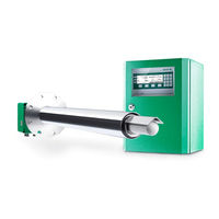
Enotec COMTEC 6000 Assembly, Installation And Operation Manual (67 pages)
O2 / COe Analyzer System
Brand:
Enotec
| Category:
Analytical Instruments
| Size: 6 MB
Table of Contents
Table of Contents
3
1 System Description
4
System Overview of the COMTEC 6000
4
Measuring Principles
6
Intended Use of COMTEC 6000
6
Safety Hazards
7
Disruption of the Process
7
Storage Instructions
7
Name Plates
8
2 Installation
9
Installation Requirements for Electronic Unit
9
Installation of Probe Signal Cable FEP-0007/8
10
Access to the Terminals
11
Ferrite Sleeves (EMC)
11
Wiring Diagram of the COMTEC 6000 System
13
Installation of the Probe
14
Mounting of the Counter Flange at the Duct
14
Adjustment of the Probe Filter Head
15
Probe Protection Tube at the Mounting Flange
15
Insulating the Protection Tube Outside the Duct
16
Electrical Connections of the Probe
17
Requirements for Pneumatic Cable FEP-0002
17
Preparation of the Pneumatic Cable
18
Pneumatic Connections of the Probe
18
Pneumatic Connections of Electronic Units
19
3 Initial Operation
20
Checklist before Commissioning the System
20
System Power up
20
Display - Probe Heating Phase
20
Display - Measuring Mode
21
Keypad and Display
21
Status Leds
21
Softkey Symbols
21
System Code
21
4 Software Overview and Explanations
22
Software Overview - SYS-MENU
22
Software Explanations - SYS-MENU
26
O 2 Measuring Ranges (Scaling)
26
Limit Alarm Settings
26
O 2 Sensor Calibration Values
26
Mvalueasuring Valuvalue Avvalueraging for (O 2 / CO Value )
26
Ma Output on Systerrorsm Errorsrrors (O 2 and CO Errors )
27
CO E Measuring Ranges (Scaling)
27
CO E Sensor Calibration Values
27
Time Per Test Gas Apply
27
Delay Time to Process
27
Pre-Purge Time
27
Enotec Remote
29
Measuring Units
29
Language
29
Change System Code
29
Load Factory Settings
30
Set CO Measurement to Off/On
30
Service
30
System Checks
31
Cal Menu
31
Calibration Menu - Display Overview
32
1-Point Calibration (O And/Or CO ) (Manual)
33
5 Service and Maintenance
34
Exchange Fuses
34
Pressure and Flow Rates for Test Air And/Or Reference Air
35
Position of the Adjustment Valves
36
Adjusting Flow Rate (SME-54)
36
Replacing the Filter
37
Replacing the Probe
38
Exchange of Probe Inner Part
39
Replacing the O Sensor
40
Replacing the CO Sensor
41
Seal the CO Sensor Guide Tube
42
Relay Outputs / Functions and Correlation
43
6 Status Messages
44
Alarm Messages
46
Service Messages
46
7 Troubleshooting
47
Technical Data
49
Technical Specifications - Electronic Unit
49
Technical Specifications - Probes
50
Requirements of the Gas Supply
51
Dimensional Drawings
52
Electronic Units
52
Dimensional Drawing of Probes Kes600X
53
Counter Flanges
54
Dimension of Protection Tube Flanges
55
Probe Components
56
Probe Inner Parts Assembly
57
Gas Plans
58
Spare Parts
61
Mounting Plates of SME-53 Electronic Unit
61
Mounting Plates of 19" Rack SME-57
63
Display Board
64
Warranty
65
Declaration of Conformity
66
Index
67
Advertisement
Advertisement
Related Products
Enotec COMTEC 6000 ATEX GasEx
Enotec COMTEC 6000 DustEx
Enotec AQUATEC 1000
Enotec OXITEC 5000 Series
Enotec OXITEC 5000+
Enotec OXITEC ECONOMY
Enotec Categories
Measuring Instruments
Analytical Instruments
More Enotec Manuals
Login
Sign In
OR
Sign in with Facebook
Sign in with Google
Upload manual
Upload from disk
Upload from URL