Table of Contents
Advertisement
Quick Links
CENTRAL
Model BVR
4.3 K-factor -
Fast Response Residential
Pendent, Rec. Pendent & Concealed Glass Bulb Automatic Sprinkler
Tyco Fire Products --- www.centralsprinkler.com
451 North Cannon Avenue, Lansdale, Pennsylvania 19446 --- USA
Customer Service/Sales: Tel: (215) 362-0700 / Fax: (215) 362-5385
Technical Services: Tel: (800) 381-9312 / Fax: (800) 791-5500
General
Description
The Central Model BVR, 4.3 K-factor
Residential Pendent, Recessed Pendent
and Concealed sprinklers are decorative
glass bulb sprinklers designed for use in
residential occupancies such as homes,
apartments, dormitories, and hotels.
They are to be used in wet pipe residential
sprinkler systems for one- and two-family
dwellings and mobile homes per NFPA
13D; wet pipe residential sprinkler
systems for residential occupancies up to
and including four stories in height per
NFPA 13R; or, wet pipe sprinkler systems
for the residential portions of any occu-
pancy per NFPA 13.
The recessed version of the Model BVR
Residential Pendent Sprinkler is obtained
by utilizing the Model BVR Residential
Pendent Sprinkler in combination with the
Model BV Res./QR Recessed Escutch-
eon Assembly. The recessed version of
the Central Model BVR using a Model BV
Res./QR Recessed Escutcheon provides
up to 3/8 inch (9,5 mm) of total adjust-
ment from the flush pendent position.
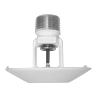
The concealed version of the model BVR
Residential Pendent Sprinkler is obtained
by utilizing the Model BVR Residential
Pendent Sprinkler in combination with the
Model BVR Concealed Cover Plate.
Operation: The glass bulb contains a fluid
which expands when exposed to heat.
When the rated temperature is reached,
the fluid expands sufficiently to shatter the
glass bulb, which then allows the sprinkler
to activate and flow water. For concealed
applications, the cover plate, which is
normally soldered to the retaining clip and
attached to the deflector of the BVR
Residential Sprinkler, falls away to expose
the sprinkler assembly.
WARNING
The BVR Residential Pendent Sprin-
klers described herein must be
installed and maintained in compliance
with this document, as well as with the
applicable standards of the National
Fire Protection Association, in addition
to the standards of any other authori-
ties having jurisdiction. Failure to do so
may impair the integrity of these
devices.
Because of the above cited stipulations
and the varied nature of residential
type architecture, there will be some
compartment designs which cannot be
fully sprinklered in accordance with the
recomendations of NFPA 13, NFPA
13D, or NFPA 13R. In the event of this
condition, consult the authorities
having jurisdiction for guidance and
approval.
The owner is responsible for maintain-
ing their fire protection system and
devices in proper operating condition.
The installing contractor or sprinkler
manufacturer should be contacted
relative to any questions.
Technical
Data
Sprinkler Identification Number
SIN C2296
Approvals
UL & ULC Listed. NYC Approved
(Refer to the Design Criteria Section)
Maximum Working Pressure
175 psi (12,1 bar)
Pipe Thread Connection
1/2 inch NPT
Discharge Coefficient
1/2
K = 4.3 GPM/psi
(61,9 LPM/bar
Temperature Ratings
Sprinkler: 155°F/68°C
Concealed Cover Plate: 135°F/57°C
Finishes
Sprinkler: White Polyester, Chrome
Plated, or Natural Brass
Recessed Escutcheon: White Coated,
Chrome Plated, or Brass Plated
Concealed Cover Plate: Chrome or Brass
Plated, White or Custom Painted
BVR
Residential
Pendent,
Rec. Pendent &
Concealed
Sprinklers
1/2
)
Physical Characteristics
The Model BVR Residential Pendent
Sprinkler utilizes a dezincification resistant
(DZR) bronze frame and a 3 mm bulb.
The sprinkler frame orifice is sealed with a
gasketed spring plate (Belleville Seal)
consisting of a beryllium nickel disc spring
that is sealed on both its inside and
outside edges with a Teflon
compression screw is bronze, and the
deflector is brass. The concealed cover
plate and retaining clip is copper.
7-02
TM
gasket. The
No. 4-3.1
Advertisement
Table of Contents

Related Manuals for Tyco Fire Product central bvr


Summary of Contents for Tyco Fire Product central bvr
- Page 1 7-02 CENTRAL Model BVR 4.3 K-factor - Fast Response Residential Pendent, Rec. Pendent & Concealed Glass Bulb Automatic Sprinkler Tyco Fire Products --- www.centralsprinkler.com 451 North Cannon Avenue, Lansdale, Pennsylvania 19446 --- USA Customer Service/Sales: Tel: (215) 362-0700 / Fax: (215) 362-5385 Technical Services: Tel: (800) 381-9312 / Fax: (800) 791-5500 Fire Protection Association, in addition General...
- Page 2 Table 1 - BVR Pendent & Recessed Pendent Design Hydraulic Design Requirements for NFPA 13D & NFPA 13R Occupancies Criteria Minimmum Design Flow/Pressure The Model BVR Residential Pendent, Recessed Pendent, and Coverage Concealed Sprinklers are UL, ULC Listed and NYC Approved Area Single Sprinkler Multiple Sprinklers...
- Page 3 Questions concerning sprinkler installation and usage Table 2 - BVR Concealed Pendent Hydraulic criteria, which are not covered by the following instructions, Design Requirements for NFPA 13D & NFPA 13R should be submitted to Central Sprinkler. Include sketches Occupancies and technical details as appropriate. In some instances, the requirements of this document may Minimmum Design Flow/Pressure concern specifications which are more stringent and which...
- Page 4 Figure 5 - Sprinkler Location for Sloped Ceiling Note the minimum distance between sprinklers changes by A — NFPA minimum of 4" (verify “G” dimension minimum of the angle of the slope. Verify the Listed flows and pressures 4"), maximum 1/2 of the Listed spacing that the sprinkler for “maximum”...
- Page 5 Figure 7 - Spacing for Sprinkler at the Peak of a Sloped Ceiling First verify that the sprinkler at the peak is considered to be “Acceptable” or “Obstructed” by the sloped ceiling in accordance with Figure 12 Graph. Measure horizontally from the deflector to the sloped ceiling, this is equal to the “D”...
- Page 6 Figure 10 - Minimum Distance Between Sprinklers on Intersecting Ceilings First verify that “D” is “Acceptable” or “Obstructed” per Figure 12 for the horizontal ceiling sprinkler and Figure 13 for the sloped ceiling sprinkler. If “Acceptable”, Figure 10 applies. If “Obstructed”, per Figure 12 or 13, then “D” is to be considered the area of coverage.
- Page 7 Figure 13 - Obstruction to Discharge by Intersecting Flat Ceiling If “D” is “Obstructed” per Figure 13 Graph, then “D” is to be considered the area of coverage and additional sprinklers 20' x 20' along the horizontal ceiling will be necessary. Only if “D” is 18' x 18' Acceptable “Acceptable”...
- Page 8 Care & Limited Ordering Maintenance Warranty Information (Continued) Products manufactured by Tyco Fire Ordering Information: When placing Products are warranted solely to the an order, indicate the full product Sprinklers which are found to be original Buyer for ten (10) years name.
Need help?
Do you have a question about the central bvr and is the answer not in the manual?
Questions and answers