Table of Contents
Advertisement
Quick Links
Advertisement
Table of Contents

Related Manuals for DOGA MDT Series


Summary of Contents for DOGA MDT Series
- Page 1 MDT series MDTC38 INSTRUCTIONS MANUAL...
- Page 2 IMPORTANT The tool delivered with this manual may have been modified for specific needs. In that case, please give us the tool code number written on our shipping note or the approximate tool delivery date when you place an order for a new similar tool or for spare parts. In that way, you will be sure to get the required tool and/or spare part.
-
Page 3: Table Of Contents
Instructions manual MDT Series & MDTC38 INDEX SAFETY RULES ........................5 Work Area ........................5 Electrical Safety ......................5 Personal Safety ......................5 Tool use and Care ......................6 Service ........................... 6 Specific safety rules ......................6 PRODUCT ..........................7 MAIN FEATURES ........................ - Page 4 Instructions manual MDT Series & MDTC38 7.12 Network settings ......................57 7.13 Monitoring ........................58 7.14 Remote control & Auto customizing ................60 7.15 Remote : Back up / Restore / Power Reset / Factory reset ........... 63 7.16 General Settings : Date / Storage / Options ..............64 7.17...
-
Page 5: Safety Rules
Instructions manual MDT Series & MDTC38 SAFETY RULES ENGLISH WARNING! Read and understand all instructions. Failure to follow all instructions listed below, may result in electric shock, fire and/or serious personal injury SAVE THIS INSTRUCTIONS 1.1 Work Area Keep your work area clean and well lit. Cluttered benches and dark areas invite accidents. -
Page 6: Tool Use And Care
Instructions manual MDT Series & MDTC38 Remove adjusting keys or switches before turning the tool on. A wrench or a key that is left attached to a rotating part of the tool may result in personal injury. Do not overreach. Keep proper footing and balance at all times. Proper footing and balance enables better control of the tool in unexpected situations. -
Page 7: Product
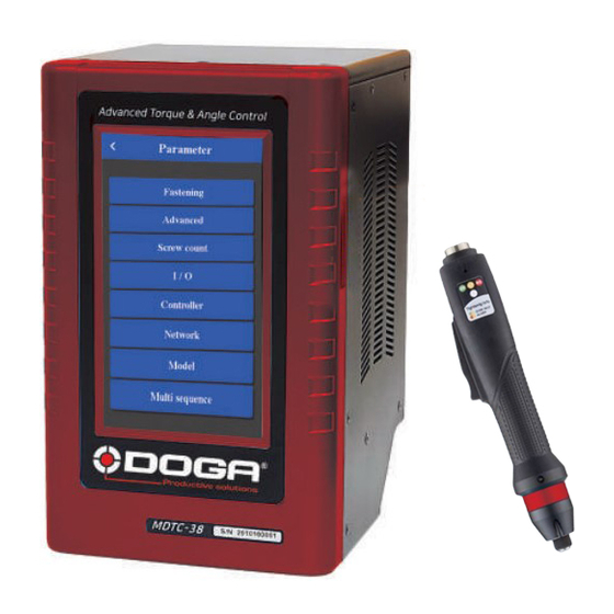
Instructions manual MDT Series & MDTC38 PRODUCT It consist of DC Servo screwdriver and controller as a complete system. Screwdriver packing : x1 screwdriver x1 CE declaration of conformity x1 calibration test certificate (original to be preserved) Controller packing :... -
Page 8: Mdt Screwdrivers
Instructions manual MDT Series & MDTC38 MDT SCREWDRIVERS 4.1 General specification Item Specification Electric power DC38V, 5A max Motor Swiss DC servo motor Torque tranducer Built-in Angle encoder Built in Speed Autospeed by torque setting or manual 4.2 Model specification Gear ratio ( 1/16 ) –... - Page 9 Instructions manual MDT Series & MDTC38 ● Pistol grip hand held (Trigger start) Torque Speed Weight Model Bit Socket Controller (N.m) (rpm) MDTP3204 0.4~4.5 100~1800 Hex 1/4” MDTP3206 0.6~6.5 100~1250 Hex 1/4” MDTP3211 1.5~11.5 50~690 1060 Hex 1/4” MDTP3216 2~16...
-
Page 10: Max Allowed Axial Force
Instructions manual MDT Series & MDTC38 ● Spindle for automation (Remote start by I/O) Torque Speed Weight Model Bit Socket Controller (N.m) (rpm) MDTA3204 0.4~4.5 100~1800 1070 Hex 1/4” MDTA3206 0.6~6.5 100~1250 1065 Hex 1/4” MDTA3211 1.5~11.5 50~690 1170 Hex 1/4”... -
Page 11: Auto Speed By Torque Setting Under The Each Test Condition
Instructions manual MDT Series & MDTC38 4.4 Auto Speed by torque setting under the each test condition ◆ Speed range : Available setting range by manual ◆ Auto speed by torque setting : Safe speed not exceeding over torque by rotation inertia... - Page 12 Instructions manual MDT Series & MDTC38 60429 08/21...
-
Page 13: Screwdrivers Overall Dimensions
Instructions manual MDT Series & MDTC38 4.5 Screwdrivers overall dimensions 4.5.1 Straight MDT and angle head MDTH MDT3204-A MDTH3204-A 60429 08/21... - Page 14 Instructions manual MDT Series & MDTC38 MTD3206-A/L MDTH3206-A/L MDTH3206-Q/L 60429 08/21...
- Page 15 Instructions manual MDT Series & MDTC38 MDT3211, 3216, 3220, 3224-A/L MDTH3211, 3216, 3220, 3224-A/L MDTH3211, 3216, 3220, 3224-Q/L 60429 08/21...
- Page 16 Instructions manual MDT Series & MDTC38 MDT3245, 3264-Q/L MDTH3245, 3264-Q/L 60429 08/21...
-
Page 17: Pistol Mdtp
Instructions manual MDT Series & MDTC38 4.5.2 Pistol MDTP MDTP3204, 3206-A/D MDTP3204, 3206-A/U MDTP3204, 3206-Q/D MDTP3204, 3206-Q/U 60429 08/21... - Page 18 Instructions manual MDT Series & MDTC38 MDTP3211, 3216, 3220, 3224-A/D MDTP3211, 3216, 3220, 3224-A/U MDTP3211, 3216, 3220, 3224, 3236-Q/D MDTP3211, 3216, 3220, 3224,3236-Q/U 60429 08/21...
- Page 19 Instructions manual MDT Series & MDTC38 MDTP3245, 3264-Q/D MDTP3245, 3264-Q/U 60429 08/21...
-
Page 20: Spindles Mdta
Instructions manual MDT Series & MDTC38 4.5.3 Spindles MDTA MDTA3204, 3206-A with telescopic cushion option 60429 08/21... - Page 21 Instructions manual MDT Series & MDTC38 MDTA3211, 3216, 3220, 3224, 3236 -A & -Q with telescopic cushion option 60429 08/21...
- Page 22 Instructions manual MDT Series & MDTC38 MDTA3245, 3264-Q with telescopic cushion option 60429 08/21...
-
Page 23: Mdt Screwdriver Cable
Instructions manual MDT Series & MDTC38 MDT SCREWDRIVER CABLE 5.1 Specification Existing in several length :standard 3 meters and extra long 5 meters and 8 meters. Cable with rectangular section to avoid twisting No sense of connection (same connector on both side) Keying Important : screwdriver max torque can be lower than it’s specification by 5% and 20% for... -
Page 24: Installation
Instructions manual MDT Series & MDTC38 5.2 Installation Cable management should be done in a way to avoid unormal strength and twist applied to cable than natural cable bending. An appropriate cable management will Use appropriate accessories from As example below :... -
Page 25: Controller Mdtc
Instructions manual MDT Series & MDTC38 CONTROLLER MDTC 6.1 Specification Model : one controller MDTC38 to drive all MTD screwdrivers or spindles models. no Item Detail model MDTC38 Input AC230V, 50/60Hz 2.5A DC38V 3.5A – 1 output for 1 screwdriver... -
Page 26: Controller Layout And Connectors
Instructions manual MDT Series & MDTC38 6.2 Controller layout and connectors Screwdriver connector RS232 SD card protected with a closure Inputs plate Outputs Ethernet Voltage supply Vertical mounting on the back side : Standard Option Option 60429 08/21... -
Page 27: Operation
Instructions manual MDT Series & MDTC38 OPERATION 7.1 Getting started at first power on or after screwdriver change. It is really important to initialize the controller and driver as a set, before attempting to make any settings, as the information stored within the controller during testing at time of manufacture may not correlate with the driver shipped with the system. - Page 28 Instructions manual MDT Series & MDTC38 Torque unit setting Default torque unit is N.m If you need to set a different torque unit, continue setting as follows : • Click on • Enter Login with default password ‘0’ • Enter Login with default password ‘0’...
-
Page 29: Operation Screen
Instructions manual MDT Series & MDTC38 7.2 Operation screen Menu Preset(Model) # 1~15 Fastening result. OK/NG/Ready Torque monitoring, Graph Target torque, Speed Fastening Time(ms), Angle Screw count, Snug angle Date & Time Real-time monitoring data and target data display on screen. - Page 30 Instructions manual MDT Series & MDTC38 ⚫ Touch screen field Login to Menu ( Default PW : 0 ) Last count cancel Preset or Job(Model) # select Real-time 60429 08/21...
-
Page 31: Presets Or Model Select
Instructions manual MDT Series & MDTC38 7.3 Presets or Model select Before use Model mode, operator require to change parameter, (Parameter>Controller> “Model select” On) There are 15 presets of program. Each preset contains the following parameters Each preset # consist of the total 30 parameters in two group... -
Page 32: Parameters
Instructions manual MDT Series & MDTC38 7.4 Parameters Parameter menu require password to log in the initial factory setting is “ 0 “ for password The password can be changed once log in. There are approx.. 950 address for each parameters. - Page 33 Instructions manual MDT Series & MDTC38 60429 08/21...
- Page 34 Instructions manual MDT Series & MDTC38 60429 08/21...
-
Page 35: Fastening Settings
Instructions manual MDT Series & MDTC38 7.5 Fastening settings Parameters listed on A and B pages for each Preset from 1 to 15 Preset selection Type Unit Range Initial Description Control type TC/AM : torque control/ angle monitoring AC/TM: angle control/ torque monitoring... - Page 36 Instructions manual MDT Series & MDTC38 Max angle Unit Range Initial degree 0 ~ 20000 Description Maximum angle to be OK in TC/AM mode Angle for Free speed Unit Range Initial degree 0 ~ 20000 Description Angle for Free speed...
-
Page 37: Advanced Functions
Instructions manual MDT Series & MDTC38 7.6 Advanced functions: Free reverse rotation, Engaging torque detection, Angle after torque up Thread tapping 4 extra fonctions can be set independantly for each Preset ① ② ③ Fastening 7.6.1 Free reverse rotation before Fastening... -
Page 38: Engaging Torque Detection
Instructions manual MDT Series & MDTC38 7.6.2 Engaging Torque detection It is possible only when the screw engaging provide significantly higher torque than previous free run. Speed Unit Range Initial Tool range Description Tool rotation speed Torque Unit Range Initial 0 ~ 50 Engaging torque setting by percentage of target torque –... -
Page 39: Thread Tapping
Instructions manual MDT Series & MDTC38 7.6.4 Thread tapping This function is dedicated to trough hole tapping with a torque pic during thread tapping. TC/AM program will start once the tapping is done. Typical thread tapping graph It is not the case in the trace above, but the tapping torque can be higher than target torque (tapping... -
Page 40: Multi Sequence Settings
Instructions manual MDT Series & MDTC38 7.7 Multi Sequence settings Multi sequence provide a cycle of fastening by a start signal. Total 10 steps of programing is allowed in MA(Multi A) and MB(Multi B) presets To program, select the command and required parameter on each step. -
Page 41: Model Settings
Instructions manual MDT Series & MDTC38 7.8 Model settings They are 15 sequencing models of 20 steps with assignable tightening program batch counting and logical IO management. Model should be activated in controller parameters. The digital inputs for preset # select becomes model # select automatically. - Page 42 Instructions manual MDT Series & MDTC38 ◆ Command details Command Description Data 1 Data 2 0 : No output → NG 1 : Active High Input # select 2 : Active Low Input Mapping digital Input from 1 - 8...
-
Page 43: Screw Count Settings
Instructions manual MDT Series & MDTC38 7.9 Screw count settings Screw count parameters are set for presets and models. Sensor signal select : Count start(IN) / end(OUT) No signal, auto start (Auto) - auto reset to total number after “0”... - Page 44 Instructions manual MDT Series & MDTC38 Port Count signal (OUT) : count complete signal can be set with 4 different type of signals Count complete(500ms) Torque up + Count complete Count complete(100ms) Screw missing alarm Count complete(500ms) : it provides 500ms of pulse type count complete signal after fasten all set numbers.
-
Page 45: Controller Settings
Instructions manual MDT Series & MDTC38 7.10 Controller settings 60429 08/21... - Page 46 Instructions manual MDT Series & MDTC38 Driver ID Unit Range Initial 1 ~ 99 Description MDC ID used to identify ethernet data communication. Driver model Unit Range Initial Screwdriver list Unknown Description Screwdriver model : to be specified to pair screwdriver with controller...
- Page 47 Instructions manual MDT Series & MDTC38 60429 08/21...
- Page 48 Instructions manual MDT Series & MDTC38 Forward run time limit Unit Range Initial 0 - 60 Run limit to forward rotation – It prevent the continuous running over the Description preset time. The driver stops automaticaly at the preset time and...
- Page 49 Instructions manual MDT Series & MDTC38 60429 08/21...
- Page 50 Instructions manual MDT Series & MDTC38 Selection on panel Unit Range Initial OFF- ON Description OFF : disable touch screen ON : allow touch screen use Reverse lock (handheld only) Unit Range Initial YES - NO Description YES will disable the reverse rotation switch on screwdriver.
- Page 51 Instructions manual MDT Series & MDTC38 Led/light on time Unit Range Initial 0 ~ 30 Description Screwdriver LED lamp off timer (used only with pistols MDP) 0 = lamp off timer disable. Event data select Unit Range Initial List Select the events to be send by ‘auto data output’ and saved on the SD Description card.
- Page 52 Instructions manual MDT Series & MDTC38 Model selection mode Unit Range Initial OFF- ON ON : model selection on operation screen or IO’s Description OFF : Preset and MA/MB selection on operation screen or IO’s Preset/Model selection on panel Unit...
-
Page 53: I/O Settings
Instructions manual MDT Series & MDTC38 7.11 I/O settings Inputs Note : Inputs 9 to 15 are ‘unassigned’ and are not listed in this menu as they cannot be set differently. So inputs 9 to 15 can only be used in models... - Page 54 Instructions manual MDT Series & MDTC38 Outputs 60429 08/21...
- Page 55 Instructions manual MDT Series & MDTC38 MDC 25P I/O schematic The digital I/O provide the free assignment feature for 8 Inputs and 8 Outputs. Factory setting of I/O assignments are as following. To validate changing I/O, turn the power OFF and ON again.
- Page 56 Instructions manual MDT Series & MDTC38 Binary coding with 5 inputs to select preset # and Mode (identical for Model) Input Torque select Torque select Torque select Torque select Multi Preset # sequence Multi A Multi B ◆ Binary coding with 3 outputs for error codes in 7 groups...
-
Page 57: Network Settings
Instructions manual MDT Series & MDTC38 7.12 Network settings Mode Unit Range Initial STATIC - DHCP STATIC Description STATIC : IP address should be set manually on controller DHCP : if controller is connected to a LAN with a DHCP router... -
Page 58: Monitoring
Instructions manual MDT Series & MDTC38 7.13 Monitoring To monitor fastening data and I/O, click and go to There are three(3) real-time monitoring menu and one error history. Graph : torque, Angle, Speed and current Input & output status Network : RS-232 & Ethernet settings Error : latest 8 error history ◆... - Page 59 Instructions manual MDT Series & MDTC38 ◆ I/O Status monitoring The I/O & tool operation signals are displayed when they are activated The temperature of the motor surface is also displayed. Torque sensor digital value is also monitored Tightening and loosening total counter for connected screwdriver ◆...
-
Page 60: Remote Control & Auto Customizing
Instructions manual MDT Series & MDTC38 7.14 Remote control & Auto customizing Remote menu provides remote tool operation, Auto customizing parameters to have highest cycle time and resets. Click , and go to group ◆ Remote The tool and output signal can be operated remotely by click the screen. - Page 61 Instructions manual MDT Series & MDTC38 ◆ Auto customizing parameters Simulation & modification window MD tool has the auto speed setting feature against torque setting not to provide any over torque by speed shock. This auto speed is safe speed on the hard joint condition. On the real application, this setting can be changed manually.
- Page 62 Instructions manual MDT Series & MDTC38 Speed Torque time ① Select Preset # to modify parameter settings ② Select one of Soft & Hard joint condition when it is obviously clear or both together when it is not clear to be clarified, then click START ③...
-
Page 63: Remote : Back Up / Restore / Power Reset / Factory Reset
Instructions manual MDT Series & MDTC38 7.15 Remote : Back up / Restore / Power Reset / Factory reset ◆ Backup Parameter back up save in SD-Card. Save on \SD-Card\PARAM folder. Back up file name : yyyymmdd.csv Only one file per day (latest backup erase previous one) ◆... -
Page 64: General Settings : Date / Storage / Options
Instructions manual MDT Series & MDTC38 7.16 General Settings : Date / Storage / Options To modify Date, Time and backlight brightness , Click ◆ Date and time System date and time can be modified. 60429 08/21... - Page 65 Instructions manual MDT Series & MDTC38 ◆ Options LCD brightness Unit Range Initial 1-100 Description Manual LCD backlight brightness adjustment SD card Unit Range Initial OFF ON Description In order to save the fastening data, Select ON of SD card and select the items to be saved on the SD card ;...
-
Page 66: General Settings : Barcode & Barcode Step
Instructions manual MDT Series & MDTC38 7.17 General Settings : Barcode & Barcode Step The barcode information can select the Preset or Model by the setting. In order to use barcode scanner, there are some parameters to be selected prior to the barcode setting. - Page 67 Instructions manual MDT Series & MDTC38 ◆ Barcode Step setting In model operation for Barcode step Registration of barcode dedicated to model step. Total number of barcode registration : up to 30 Max number of barcode data length : 32 characters ( including CR data ) Barcode number Ex: Model barcode step value set 1.
-
Page 68: Sd Memory Card Tightening Datas Saving
Instructions manual MDT Series & MDTC38 7.18 SD memory card tightening datas saving SD memory card specification SD card type Size Format Industrial grade Class 10 Max 32GB FAT32 ◆ Storage Check SD card informations and available memory Important : Format will delete all datas saved on memory card To avoid loosing datas please make a copy before. -
Page 69: Firmware Update
Instructions manual MDT Series & MDTC38 Example csv file opened with a spreadsheet software ** The last scanning data is recorded together with every fastening data FIRMWARE UPDATE 1) Remove the SD card for data saving and use the new SD card for firmware update only. -
Page 70: Torque Calibration And Compensation
Instructions manual MDT Series & MDTC38 TORQUE CALIBRATION AND COMPENSATION ◆ Torque calibration : It is the master calibration for whole torque range of the tool, saved in the tool memory. The F/R switch should be at Reverse position before writing the new value. - Page 71 Instructions manual MDT Series & MDTC38 ◆ Torque compensation : Individual torque tuning on each preset. Saved in the controller Torque compensation can be used when : The reading on the torque meter is variable according to the fastening condition on each preset, and it should be decreased or increased together on other presets, the torque compensation is useful in parameter setting of each preset.
-
Page 72: Error Code
Instructions manual MDT Series & MDTC38 ERROR CODE 10.1 System error Code Error message Description How to reset Power reset. Transducer sensor If error remain , check the Transducer sensor problem. error transducer sensor Over current Over current during driver run. -
Page 73: Fastening Error By The Pattern Setting
Instructions manual MDT Series & MDTC38 10.2 Fastening error by the pattern setting Code Error message Description How to reset Run time limit (Forward) Over time limit on parameter Check the parameter Run time limit (Reverse) Over time limit on parameter... -
Page 74: Web Server
Instructions manual MDT Series & MDTC38 WEB SERVER - Web server software is added in the MDTC controller - Web surfing program of Chrome or Firefox is more recommended. - Access to the IP address of the MDC controller via the web browser. -
Page 75: Registers List Summary
Instructions manual MDT Series & MDTC38 REGISTERS LIST SUMMARY Group Parameter Address A001 – A225 1. Fastening Preset #1 to #15 A226 – A233 Input 2. I/O A234 – A241 Output A242 – A247 3. Screw count Number & cycle start A250 –... -
Page 76: Open Protocol Server
Instructions manual MDT Series & MDTC38 13.2 OPEN PROTOCOL Server MDTC controller is capable of connecting to the host controller through Ethernet using hereunder listed MID. Please refer to dedicated instruction manual. 60429 08/21... -
Page 77: Maintenance
Check how to reset the alarm in the error code chapter 10. Caution All repair tasks requiring the box to be opened must be carried out by DOGA or a contractor authorized by DOGA. If, despite reading this manual, you are unable to solve a problem, please contact the DOGA after- sales department. -
Page 78: Phone Support
For any questions about using the device Please contact your technical salesperson My client area on www.doga.fr Go to your client area on www.doga.fr, click “Your contacts”, then select your specific technical salesperson contact depending on the device type. For any questions about repairs Please contact your After-sales department contact. -
Page 79: On-Site Repair
If you require an on-site intervention, please contact the After-sales department. My client area on www.doga.fr Go to your client area on www.doga.fr, click “Your contacts”, then select your specific After-sales department contact depending on the device type. Our services will organize the intervention. -
Page 80: Standards
Instructions manual MDT Series & MDTC38 STANDARDS 15.1 Manufacturer details Importer: DOGA Address: ZA Pariwest 8 avenue Gutenberg CS 50510 78317 MAUREPAS CEDEX - FRANCE 15.2 Markings MDT / MDTC Equipment name Type Equipment reference Serial no. Unique equipment serial number... -
Page 81: Weee Recycling And End Of Service Life
Collection and recycling scheme In compliance with the French Environmental Code covering professional Waste Electric and Electronic Equipment (WEEE) (art. R543-195 et seq.), DOGA is a member of ECOSYSTEM, an eco-organization approved by public authorities under the conditions defined by art. R564-197. - Page 84 © DOGA | DOC.60429-08/21...
Need help?
Do you have a question about the MDT Series and is the answer not in the manual?
Questions and answers