
Related Manuals for DOGA BS-5C


Summary of Contents for DOGA BS-5C
- Page 1 Instruction manual BS-5C COLOR ID BIT TRAY 60327-04/20 www.dogassembly.com 433000-10/19...
-
Page 2: Table Of Contents
CONTENTS Symbols......................5 1. INFORMATION ...................... 6 1.1 IMPORTANT....................6 1.2 Product reference................... 6 1.3 General equipment description............6 1.3.1 Master mode operation ............. 7 1.3.2 Slave mode operation..............7 1.4 Standard equipment presentation............7 1.5 Packing list....................8 1.6 Technical specifications................. 8 2. STARTING UP ...................... 10 2.1 Workstation description............... - Page 3 7. STANDARDS ......................34 7.1 Manufacturer details................34 7.2 Markings....................34 7.3 Transport and storage................34 7.3.1 Transport..................35 7.3.2 Storage..................35 7.4 WEEE recycling and end of service life..........35 7.4.1 Collection and recycling scheme..........35 7.4.2 Collection points................ 36 60327-04/20 BS-5C color ID bit tray...
- Page 4 8. ANNEXES ......................37 Annex 1 - Sub D25 connector description..........37 Annex 2 - Input / output program correspondence table......38 Annex 3 - Configuration of equipment connected to the bit tray..39 60327-04/20 BS-5C color ID bit tray...
-
Page 5: Symbols
Wear personal protection equipment This symbol indicates the need to wear protective gloves. Warning This warning statement indicates a moderate risk that may lead to severe or fatal injuries if not avoided. 60327-04/20 BS-5C color ID bit tray... -
Page 6: Information
If this is the case, when ordering a renewal or spare parts, please indicate the tool item code featured on the delivery document, or contact DOGA at +33 1 30 66 41 41 indicating the approximate delivery date. You will then be sure to get the required tool and/or parts. -
Page 7: Master Mode Operation
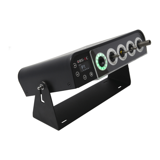
1.4 Standard equipment presentation Button up Modbus indicator Button down Screwdriver locked Menu opening / Validation Bit presence indicator Back / Cancel LED ring indicator x 5 Operating mode indicator Bit slot x 5 Screwdriver program 60327-04/20 BS-5C color ID bit tray... -
Page 8: Packing List
1.6 Technical specifications Dimensions in millimeters Electric specifications Power supply 24 V Mains adapter 100-240 V ~ 50 - 60 Hz Plug type Europe / UK / US Consumption 25 W max Physical specifications 60327-04/20 BS-5C color ID bit tray... - Page 9 5 RGB LED ring indicators French English Italian Languages German Spanish Czech Protection class and rating Equipment class Class II: insulated casing IP 4X: equipment protected against solid IP rating objects over 1 mm 60327-04/20 BS-5C color ID bit tray...
-
Page 10: Starting Up
Eliminate the packaging in compliance with applicable national legislation. 2.3 Configuration 2.3.1 Bit customization As bit foolproofing is color coded, it is essential to use a different color marking on each bit to operate properly the bit tray. 60327-04/20 BS-5C color ID bit tray... - Page 11 Information Only original sleeves supplied by DOGA have been tested and validated for faultless operation. There are 3 sizes for the coloured heat-shrinkable sleeves in order to adapt to the bit’s diameter Size 1: 2.4 mm ≤ d ≤ 4.8 mm Size 2: 3.2 mm ≤...
-
Page 12: Slot Configuration
2.3.2 Slot configuration The BS-5C bit tray initial configuration is such that it can accept 70 mm long bits in each slot. Configuring the bit tray to bit length is done by placing stop cleats. - Page 13 Choice A: Standard bit holder for hexagonal ¼” bits Choice B et D : Solid bit holder machined according to the following drawing Choice C : Solid bit holder machined according to the following drawing 60327-04/20 BS-5C color ID bit tray...
- Page 14 Removal of the bit tray lower part Place the bit tray upside down on a Remove the 4 screws under the bit table. tray. Remove the transparent protective Remove the lower part of the bit tray. crankcase. 60327-04/20 BS-5C color ID bit tray...
- Page 15 Position it so that the drill hole can be seen at the top. Insert the locating pin into the drill Rotate the bit holder to locate pin in hole on the bit holder. its housing. 60327-04/20 BS-5C color ID bit tray...
- Page 16 115 - 144 mm 65 - 84 mm ≥ 145 mm 85 - 114 mm - Refit the lower part of the bit tray and the transparent protective crankcase and tight the 4 screws. 60327-04/20 BS-5C color ID bit tray...
-
Page 17: Bit Tray Connection
Jack power supply connector, D2.1 mm x D5.5mm, 24V CC 1.5 A + voltage in the center: Ethernet RJ45 connector for Modbus (option to be released) TCP connection to the DOGA MDC controller only. Sub D 25 connector for digital inputs / outputs 5 Slots extension connector... -
Page 18: Connection To Tightening Controller
ALPHA V “QBE” Expert and ALPHA V “QBE” Advanced series. Preferably use a connecting cable dedicated to your controller model and sold by DOGA. Refer to annex 3 to configure your equipment connected to the bit tray. 60327-04/20 BS-5C color ID bit tray... -
Page 19: Installation
2.4 Installation 2.4.1 Bit tray installation We recommend fixing the BS-5C bit tray to the workstation and locking its position using the blind nuts located on its sides. The bit tray can be fixed to the workstation in several ways:... -
Page 20: Bit Installation
Normal position: footprints towards the outside Position for bits 49 to 64 mm long and in bit holders of choices B and C described in section 2.3.2: imprints towards the inside Slot blocked by a full bit holder 60327-04/20 BS-5C color ID bit tray... -
Page 21: Settings
Validation and access to the settings menu Cancel and back to the settings menu Scrolling up through the settings menus Scrolling down through the settings menus 3.2 Access to the settings menu 3.2.1 Settings menu tree structure 60327-04/20 BS-5C color ID bit tray... -
Page 22: Settings Menu Description
Bit position learning is auto-teach by selecting calibration from the menu. Calibration is in 2 steps: Empty bit tray calibration (without bits). Calibration with bits. Once these 2 steps are completed, the bits are linked to their slots. 60327-04/20 BS-5C color ID bit tray... -
Page 23: Operating Mode Configuration
Factory setting: bit assignment to the program is direct: - Program 1 corresponds to location 1 - Program 2 corresponds to location 2 - Etc… A program number can be defined for each bit. 60327-04/20 BS-5C color ID bit tray... -
Page 24: Master Mode Routing
3.5.1 Master mode routing Select the slot then, select the associated program. 3.5.2 Slave mode routing Select the program, choose the associated slot. 60327-04/20 BS-5C color ID bit tray... -
Page 25: Use
Pick the bit to use: the program is activated and the assembly tool is unlocked. If 2 bits are removed from their slot at the same time, the tool locks. If the bits are not in their respective slots, the tool is locked. 60327-04/20 BS-5C color ID bit tray... -
Page 26: Maintenance
Despite that, if the device has a malfunction, check it using the list below. Caution All repair tasks requiring the box to be opened must be carried out by DOGA or a contractor authorized by DOGA. Malfunction Action to take Bit detection does not ... - Page 27 If, despite reading this manual, you are unable to solve a problem, please contact the DOGA after-sales department. My client area on www.doga.fr Go to your client area on www.doga.fr, click “Your contacts”, then select your specific After-sales department contact depending on the device type.
-
Page 28: Spare Parts
5.4.1 For any questions about using the device Please contact your technical salesperson My client area on www.doga.fr Go to your client area on www.doga.fr, click “Your contacts”, then select your specific technical salesperson contact depending on the device type. -
Page 29: After-Sales Returns
Compliance with this procedure means that your request will be processed quickly with reduced troubleshooting costs. DOGA reserves the right to apply a trade-in discount and, when applicable, to invoice repair and packaging costs. 5.5.1 Download the after-sales return form You can download the form using one of the following links: http://service.doga.fr/syst/dogatech.nsf/liste/00184... -
Page 30: Send Your Equipment
If you require an on-site intervention, please contact the After-sales department. My client area on www.doga.fr Go to your client area on www.doga.fr, click “Your contacts”, then select your specific After-sales department contact depending on the device type. Our services will organize the intervention. -
Page 31: Warranty
5.7 Warranty DOGA guarantees its products for parts or manufacturing defects for 12 months. To benefit from this parts and labor warranty, the following conditions must be met: The device must have been used in a professional context and in ... -
Page 32: Safety
6.2 Residual risks Burn risks Handling a hot air gun when customizing bits using heat shrinkable sleeves exposes to a temperature of 90°C. We recommend handling the bits using pliers and wearing protective gloves. 60327-04/20 BS-5C color ID bit tray... -
Page 33: Contra-Indications
A person colliding with the bit tray with part of their body (not protected by safety equipment) would be exposed to risk of injury. 6.3 Contra-indications Do not cover. Do not immerse. Do not expose to liquid spray. Do not use near a heat source. 60327-04/20 BS-5C color ID bit tray... -
Page 34: Standards
All safety instructions and other instructions must be read 7.3 Transport and storage Information Your equipment may be damaged if you transport or store it in unsuitable conditions. Comply with the transport and storage information for your equipment. 60327-04/20 BS-5C color ID bit tray... -
Page 35: Transport
In compliance with the French Environmental Code covering professional Waste Electric and Electronic Equipment (WEEE) (art. R543-195 et seq.), DOGA is a member of ECOSYSTEM, an eco-organization approved by public authorities under the conditions defined by art. R564-197. You can also benefit from collection and recycling system proposed by ECOSYSTEM for WEEE originating from the professional equipment marketed by DOGA. -
Page 36: Collection Points
7.4.2 Collection points Free collection points for used electric or electronic devices are available near your company. Your local authorities can provide their addresses. 60327-04/20 BS-5C color ID bit tray... -
Page 37: Annexes
Selection 5 output Selection 6 output Selection 7 output Selection 8 output Tool available output Tool available output Alarm output (tool disable) Alarm (tool disable) Ground Ground Common inputs Common inputs Common outputs Common outputs 60327-04/20 BS-5C color ID bit tray... -
Page 38: Annex 2 - Input / Output Program Correspondence Table
Annex 2 - Input / output program correspondence table 60327-04/20 BS-5C color ID bit tray... -
Page 39: Annex 3 - Configuration Of Equipment Connected To The Bit Tray
P20 = 1 or 2 - P86 = 0 DPC Touch interface Inputs and outputs 9, 10, 11 and 12 must remain unassigned in order to create a continuous type output step to select the corresponding bit. 60327-04/20 BS-5C color ID bit tray... - Page 40 Pins F, G, H, J and P, R, S, T are used to select the assembly bit Configure the outputs using menu: Setup \ Other > I/O > 24V (Out) Out F Out G Out H Out J Configure the inputs using menu: 60327-04/20 BS-5C color ID bit tray...
- Page 41 Setup \ Other > I/O > 24V (In) In M In P In R In S In T 60327-04/20 BS-5C color ID bit tray...
- Page 42 60327-04/20 BS-5C color ID bit tray...
- Page 43 60327-04/20 BS-5C color ID bit tray...
- Page 44 Download the latest version of this user manual using the following link by scanning this QR code Or by clicking this link: http://service.doga.fr/syst/dogatech.nsf/liste/60327 © DOGA | DOC.60327-04/20 60327-04/20 BS-5C color ID bit tray...
Need help?
Do you have a question about the BS-5C and is the answer not in the manual?
Questions and answers