Table of Contents
Advertisement
Quick Links
Syncrocloser
Synchronizing System
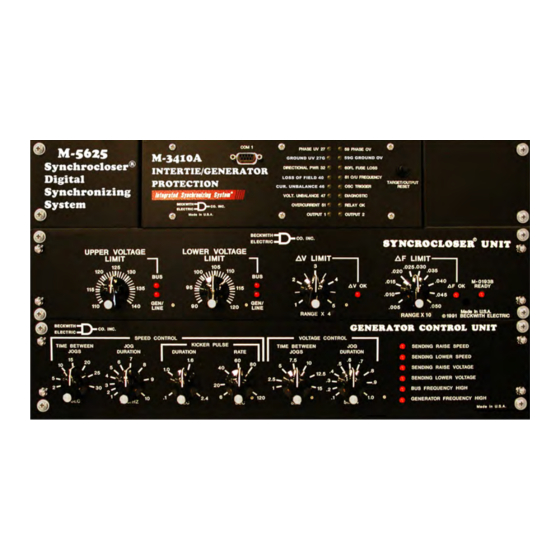
M‑5625
Integrated Synchronizing System
and Intertie Synchronizing
•
Facilitates standardization for generator and system intertie
sync check applications
•
Assure safe and accurate connection of a generator
to the power network
•
Provides accuracy and independent controls; no additional
instrumentation is required for field setting
•
Breaker closing times are field programmable
•
Local and remote serial communications (MODBUS protocol)
capability for monitoring and control functions
Digital
®
for Generator
®
SYNCROCLOSER
®
LINE
Advertisement
Table of Contents

Subscribe to Our Youtube Channel
Related Manuals for BECKWITH ELECTRIC Syncrocloser M‑5625


Summary of Contents for BECKWITH ELECTRIC Syncrocloser M‑5625
- Page 1 SYNCROCLOSER ® LINE Syncrocloser Digital ® Synchronizing System M‑5625 Integrated Synchronizing System for Generator ® and Intertie Synchronizing • Facilitates standardization for generator and system intertie sync check applications • Assure safe and accurate connection of a generator to the power network •...
-
Page 2: Standard Features
M‑5625 Digital Synchronizing System Digital Synchronizing System When the M-3410A relay is connected with Line-Line voltage input, the following functions are available (refer to Figure 7 for wiring connections). • Sync-check with Phase Angle, ∆V and ∆F with dead line/dead bus options (25) •... - Page 3 M‑5625 Digital Synchronizing System SYNCHRONIZING SYSTEM FUNCTIONS Device Setpoint Number Function Ranges Increment Accuracy Sync Check Phase Angle Window 0° to 90° 1° 1° Upper Voltage Limit 100.0 to 120.0%* 0.1% 0.5 V or 0.5% Lower Voltage Limit 70.0 to 100.0%* 0.1% 0.5 V or 0.5% Delta Voltage Limit...
- Page 4 M‑5625 Digital Synchronizing System SYNCHRONIZING SYSTEM FUNCTIONS (cont.) Device Setpoint Number Function Ranges Increment Accuracy Phase Overvoltage Pickup #1, #2 100 to 150%* 0.1% 0.5 V or 0.5% Time Delay #1, #2 1 to 8160 Cycles 1 Cycle 2 Cycles** * Of nominal voltage.
- Page 5 M‑5625 Digital Synchronizing System SYNCHRONIZING SYSTEM FUNCTIONS (cont.) Device Setpoint Number Function Ranges Increment Accuracy Controls (cont.) Speed Control Speed matching range of operation 30 to 85 Hz — — Time Between Jogs 2 to 30 seconds — ±20% of setting Jog Duration —...
- Page 6 M‑5625 Digital Synchronizing System Description • Closure of a network breaker where there is a possibility of a split of the The M-5625 Syncrocloser Digital Synchronizing system into two isolated networks having System is suitable for the automatic synchronizing different frequencies of a generator to the electric power network.
- Page 7 M‑5625 Digital Synchronizing System BUS/LINE 1 DIGITAL SYNCHRONIZING SYSTEM BUS VT CLOSE GEN/LINE VT BUS VT = BUS/LINE 1 VOLTAGE GEN/LINE VT = BUS/LINE 2 VOLTAGE = CIRCUIT BREAKER BUS/LINE 2 CLOSE = SYNCHRONIZING CLOSE COMMAND Figure 2 Automatic Synchronizing for Synchronous and Asynchronous Line and Busbars –7–...
- Page 8 M‑5625 Digital Synchronizing System DEAD CLOSE (BLACK CLOSE) SYNC AUTO MANUAL TO EXCITATION SYSTEM (AUTOMATIC VOLTAGE REGULATOR) TO GOVERNOR (TURBINE REGULATOR) 25-2 25-1 ENABLE DEAD CLOSE (ENABLE BLACK CLOSE) GENERATOR SYNCHRONIZING SYSTEM BLACK START PATH SYNC PATH NOTES: = AUTOMATIC SYNCHRONIZER CLOSE COMMAND 25-1 = SYNC CHECK RELAY CLOSE 1 COMMAND 25-2...
- Page 9 M‑5625 Digital Synchronizing System Minimum Frequency Difference The guaranteed minimum frequency difference for Auto-Sync operation is 0.0005 Hz. However, typical units consistently operate with frequency difference of 0.0001 Hz. Zero Phase Prediction Figure 4 illustrates the average closing phase error as a function of frequency difference for 80 ms, 100 ms, 200 ms, 400 ms and 800 ms breaker closing times.
-
Page 10: Sequence Of Events
M‑5625 Digital Synchronizing System Metering The Digital Synchronizing System provides metering of voltages, currents, real power, reactive power, power factor, frequency and positive sequence impedance. Metering Accuracies are: Voltage: 0.5 V or 0.5%, whichever is greater (Range 0 to 600 V) Current: 5 A rating, 0.1 A or 3%, whichever is greater (Range 0 to 14 A) 1 A rating, 0.02 A or 3%, whichever is greater (Range 0 to 2.8 A) -
Page 11: Sensing Inputs
M‑5625 Digital Synchronizing System Sensing Inputs 2 Voltage Inputs: Gen/Line and Bus voltages, nominal 120 V ac, 60 Hz (Optional 50 Hz user configurable). Will withstand 145 V ac maximum continuous voltage, 200 V ac for 1 second. Voltage transformer burden less than 0.5 VA at 120 V ac. - Page 12 M‑5625 Digital Synchronizing System Target/Status Indicators (LEDs) • UPPER VOLTAGE LIMIT BUS OK • UPPER VOLTAGE LIMIT GEN/LINE OK • LOWER VOLTAGE LIMIT BUS OK • LOWER VOLTAGE LIMIT GEN/LINE OK • V LIMIT OK • F LIMIT OK • M-0193B READY •...
-
Page 13: Electrical Environment
M‑5625 Digital Synchronizing System Tests and Standards The M-5625 Digital Synchronizing System consists of the M-0193B, M-0194 and the M-3410A components. The M-3410A meets or exceeds the following Tests & Standards, the M-0193B and the M-0194 have not been tested to all of the Tests & Standards listed below. Please contact the factory for a complete listing of applicable Tests &... -
Page 14: Atmospheric Environment
M‑5625 Digital Synchronizing System Radiated Susceptibility ANSI/IEEE 80-1000 Mhz @ 35 V/m (with Keying test) C37.90.2 2004 Output Contacts ANSI/IEEE Make 30 A for 0.2 seconds, off for 15 seconds for 2,000 operations C37.90.0 Section 6.7.1, Tripping Output Performance Requirements Atmospheric Environment Temperature IEC 60068-2-1... - Page 15 M‑5625 Digital Synchronizing System Figure 5 External Connections, Two Phase-Phase VTs –15–...
- Page 16 M‑5625 Digital Synchronizing System Figure 6 External Connections, Single Phase-Ground VTs –16–...
- Page 17 M‑5625 Digital Synchronizing System Figure 7 External Connections, Single Phase-Phase VTs –17–...
- Page 18 © 2005 Beckwith Electric Co. All Rights Reserved. 800-5625-SP-02MC1 01/13 Printed in USA...
Need help?
Do you have a question about the Syncrocloser M‑5625 and is the answer not in the manual?
Questions and answers