Advertisement
Quick Links
PROFESSIONAL
Dial Indicator / Comparator
DIAL GAUGE
Thank you for purchasing the Niigata Seiki Dial Gauge.
Used with a Magnetic Base or Indicator Stand, this gauge will show the difference in height or
position relative to a zero point set at a reference position.
■
APPLICATIONS
・Comparing parts to a master part during inspection
・Measuring machine tools positioning accuracy
●For safe and proper use of this product, please
read this instruction manual before use and follow
the procedures described. Please keep manual
where it is accessible to user for future reference.
●Keep this manual with the instrument if transferred
or leased to a third party.
●For inquiries about this product, please contact
dealer or Niigata Seiki at the address listed on the
following page.
■
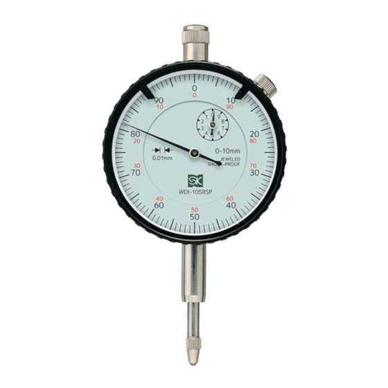
PART IDENTIFICATION, FUNCTION
① Limit Markers
④ Bezel Clamp
Screw
⑤ Revolution
Counter
② Pointer
⑥ Rev. Counter
( Needle )
Scale
③ Main Scale
( Indicator Face )
⑦ Stem
( φ8mm )
⑧ Spindle
⑨ Contact Point ( Probe )
①Limit Markers
............
For marking acceptance
range for Pass/Fail testing
②Pointer ( Needle )
.........
Shows measurement on Main
Scale
③Main Scale
Main Scale, rotate Bezel ( ⑩ )
..................
( Indicator Face )
to turn
④Bezel Clamp Screw
...
Clamps Scale to prevent
( WDI-0558SP/
rotation
WDI-1058SP/WDI-0158SP only )
⑤Revolution Counter
...
Pointer indicates Main Scale
×100
⑥Rev. Counter Scale
...
Each division is Main Scale
×100
HOW TO USE - Preparation
①Confirm that the Contact Point and Rear Plate are tightly fastened.
If loose, tighten Contact Point and Rear Plate Screws.
②Attach to the Gauge Holder using the Stem or Rear Lug.
Mounting Gauge by other than Stem or Lug will cause inaccuracy and product damage.
③Confirm that Pointer and Revolution Counter movement is smooth.
Using fingertip, gently press on Contact Point to move the Spindle up and down. Motion of
Pointers should be smooth. If it is not smooth make sure Stem is not clamped too tight, and adjust.
Also make sure Pointer is stable at set position.
④Make sure Spindle axis is perpendicular
to measured surface.
If Spindle ( Contact Point ) is not at a right
angle to surface, Gauge will not operate
properly and measurement will be inaccurate.
Always keep the Spindle axis perpendicular.
※When used to check parallelism of Milling
Machine vise, use a Magnetic Base to
mount the Gauge perpendicular to surface,
and move it out of the way during operation
to prevent interference.
HOW TO USE - Comparison Measurements
①Set Up Reference Part.
Carefully lift Spindle with fingertip, and, taking
care not to hit Spindle from the side, insert the
Reference Part or Master under Contact Point.
②Set the Origin.
Adjust the gauge mount or rotate the Bezel to
set the Gauge to "0".
③Remove Reference, and begin
measurements.
Remove Reference or Master, careful not to
shock Spindle. Insert part to be measured and
read the measurement off the Scale.
※Setting the Limit Markers
Limit Markers can be moved to show
acceptance range for measurements.
HOW TO USE - Parallelism, Flatness, Runout, etc.
①Position Contact Point on surface.
Carefully lifting Spindle with fingertip, and taking care not to hit Spindle from the side, position the
surface to be measured under the Contact Point.
②Set the Origin.
Adjust the gauge mount, or rotate the Bezel to set the Gauge to "0".
③Read the scale as the measured part is moved.
Slowly move the part while monitoring the Pointer and reading the measurement.
User Manual
WDI-10KD
WDI-0342
Model No.
WDI-10
WDI-0542
DI-1058
・Measuring runout for rotary shafts
・Checking vise parallelism on milling machines
・Measuring flatness of surfaces and assemblies
・Confirming machine tool feed distance
SAFETY NOTIFICATIONS
Throughout this manual, "
" symbol indicates
RISK OF PERSONAL INJURY OR PROPERTY
DAMAGE if not followed.
The "
" symbol indicates something which is
PROHIBITED, and the "
" symbol Indicates
REQUIRED step or necessary condition.
※Model WDI-0558SP shown
⑪ Flat Rear Plate
⑩ Bezel
[ Accessories ]
※To Use the Rear Plate with Lug,
unscrew the Standard Flat
Rear Plate screws, replace,
and use screws to secure.
⑦Stem
...........................
For holding and mounting
Gauge
⑧Spindle
........................
Shaft moves up and down
with measurement
⑨Contact Point
............
Probe which contacts
( Probe )
workpiece
⑩Bezel
Rotate to turn Main Scale ( ③ )
...........................
⑪Flat Rear Plate
............
Standard back cover
⑫Lug
..............................
Alternate mounting point
⑬Mounting Hole
............
For mounting Gauge
⑭Rear Plate with Lug
...
Accessory back cover for
mounting Gauge using Lug
Right Angle
Measured Object
Measured Object
Ex. ) Pass Range :
① Limit Markers
−0.05 to +0.15mm
② Pointer
SAFETY PRECAUTIONS
WDI-0558SP
Always follow the procedures specified below in order to prevent harm to yourself or others, and to
WDI-1058SP
prevent damage to property.
WDI-0158SP
■Content marked as follows indicates risk of injury or damage if not followed.
WARNING
■These symbols mark content that must be observed.
Denotes a prohibition – You MUST NOT do.
Read the manual and follow all instructions.
・Use of product other than as described in
the manual may cause accident.
Use only as indicator Gauge.
・Use for any purpose other than measuring
may damage or wear the instrument.
Improper use may also cause accident.
Use in an environment which meets the
following conditions:
●Temperature within range of 0~40° C、
humidity 30~70% ( non-condensing. )
●Location with minimal dust, oil, oil mist,
and protected from direct sunlight.
●Location protected from use by
children and unauthorized people.
・Use in location contrary to the above may
cause poor accuracy, damage to the
product, or may result in accident or injury.
⑫ Lug
Handle With Care.
・Do not drop or subject to shock, do not
⑬ Mounting
place under heavy objects. Damage may
Hole
cause failure or poor accuracy.
( φ6. 5mm )
PREPARATION - Mounting
⑭Rear Plate
Dial gauge must be securely mounted such as on a comparator stand or magnetic base.
with Lug
Please follow these guidelines.
Make sure Gauge holder is rigid.
・Holder must be sufficiently secure to prevent
deflection from the weight of the Gauge.
・Holder must be rigid enough to hold Gauge and
not to lift from measurement force.
・Holder support arm should be as short as possible
to prevent deflection.
※Deflection or lifting will cause measurement error
such as origin position error and inaccuracies in
measured reading.
Dial Gauge must only be attached by Stem or Rear Lug.
・Mounting of gauge by other than Stem or Lug will
cause inaccuracy and product damage.
During installation, do not over-tighten the Stem.
・Excessive force on the Stem may cause Spindle to bind.
TROUBLESHOOTING
■Origin position shifts during measurement.
・Temperature changes during measurement can cause repeatability error. Please try the following
solutions:
●Use in location with constant temperature.
●When taking measurements, periodically adjust zero point using a Master reference to correct
for temperature induced drift.
■Measurement is not stable, or measurement accuracy is poor.
・Contact Point may be worn.
Worn Contact Point will affect accuracy. Periodically check for wear, and replace if wear is
affecting measurement accuracy.
SPECIFICATIONS
Model No.
Graduation
Measurement Range
Scale
Hysteresis Error
Measuring Force
1 Revolution
1/10 Rev Indication Error
Indication Error over the Entire
Measuring Range
Repeatability
Weight
Contact Point
Replacement Contact Point Part No.
AFTER USE CARE, STORAGE
Remove any dust or dirt after use. ※Do not lubricate.
・Wipe any contamination from Spindle sliding surface using a dry cloth, or cloth moistened
with alcohol.
・To clean other surfaces, wipe with a soft dry cloth, or a cloth moistened with a mild cleaner.
Check for wear of Contact Point.
・Measurement accuracy will be affected by worn Contact Point. Regularly check for wear
and replace Contact Point if worn.
Store in provided case in a cool, dark, and dry location.
・During storage, make sure there is no force on the Spindle ( such as pushed in, or lateral force.)
・Keep away from moisture and direct sunlight, and secure from unauthorized personnel.
To maintain measurement accuracy, periodic
calibration is recommended.
Calibration interval necessary to maintain accuracy will vary
depending on frequency and conditions of use. Please follow
your companies guidelines and calibrate regularly.
Outside Japan,
Please contact distributor or place of purchase to inquire
about calibration services.
Please Observe
Indicates risk of personal injury or property damage if not followed.
Denotes a requirement – You MUST do.
CAUTION
Do not disassemble or modify.
・It may damage Gauge and cause poor
accuracy.
・If Bezel Clamp Screw is removed, internal
components may come loose and become
misaligned causing product failure.
Do not shock Spindle.
・Rapid motion, or lateral force may damage
Gauge and cause poor accuracy.
No Rapid Motion
Support Arm
WDI-10KD WDI-10 DI-1058 WDI-0342 WDI-0542 WDI-0558SP WDI-1058SP WDI-0158SP
( mm )
0.01
0.01
( mm )
10
3
±0-100
±0-50
( μm )
5
6
≦
≦
( N )
1.5
1.5
( mm )
1
0.5
( μm )
8
8
( μm )
20
14
( μm )
5
5
(g)
180
100
Steel Ball
Steel Ball
DI-CP
DI-CP
No Lateral Force
Gauge Holder
⑦Stem
Minimize Length
※Mounting Example
0.01
0.001
5
5
10
1
±0-100
0-100-0
3
2
≦
≦
1.5
2
1
0.2
9
8
10
3
16
16
20
5
3
0.3
190
Carbide Ball
WDI-W
Niigata seiki Co., Ltd.
5-3-14, Tsukanome, Sanjo, Niigata, Japan, 955-0055
Tel. : +81-256-33-5522 Fax. : +81-256-33-5518
MAIL intl.sales@niigataseiki.co.jp
URL
http://www.niigataseiki.co.jp
Advertisement

Related Manuals for Niigata seiki WDI-10KD


Summary of Contents for Niigata seiki WDI-10KD
- Page 1 PROHIBITED, and the “ ” symbol Indicates ・Rapid motion, or lateral force may damage Use in an environment which meets the dealer or Niigata Seiki at the address listed on the REQUIRED step or necessary condition. following conditions: Gauge and cause poor accuracy.
- Page 2 調整する ③長針・短針・スピンドルの動きが滑らかであることを確認する ■測定値が安定しない、測定精度外の数値を示す 指の腹で測定子をゆっくり押して上下させ、動きを確認してください。 ・測定子の磨耗が考えられます。 滑らかでない場合は、ステムを締め付けすぎている恐れがありますので、調整してください。 測定子が磨耗すると測定値に影響が出ます。定期的に磨耗確認を行い、測定値に影響が出る場合は交 また、針が設定位置で安定して静止することを確認してください。 換を行ってください。 ④測定対象に対して、 スピンドル (測定子) が垂直 本体仕様 に接するよう設置する スピンドル(測定子)が垂直に接しないと、測定値や 動作に不具合が出ます。 品 番 WDI-10KD WDI-10 DI-1058 WDI-0342 WDI-0542 WDI-0558SP WDI-1058SP WDI-0158SP 常に垂直を保つように設置してください。 目 量 (mm) 0.01 0.01 0.01 0.001 ※フライスのバイス平行確認に使用する際は、バイス 測定範囲 (mm) 直角 測定面とスピンドル(測定子)の垂直を保ちつつ、 目盛仕様 ±0-100 ±0-50...