Table of Contents
Advertisement
Quick Links
Advertisement
Table of Contents

Related Manuals for Niigata seiki LEVELNIC DL-S3


Summary of Contents for Niigata seiki LEVELNIC DL-S3
- Page 1 LEVELNIC DL-S3 OPERATION MANUAL...
- Page 3 Thank you for adopting the Niigata Seiki LEVELNIC. To bring the intrinsic performance of this device to full play when you use it, please read this manual carefully through the end and acquire a sure grip on its correct use, so that the device will serve you for many years to come.
-
Page 4: Table Of Contents
[Contents] General ........................3 Features ........................3 Names of Component Parts ..................4 Functions of Component Parts ................... 6 Variation of Measuring Range due to Movement of Reference Point ....... 10 Operation Method ..................... 12 Zero-Point Setting ..................... 14 Leveling ........................16 External Signal Output .................... -
Page 5: General
[General] This is a pendulum type high sensitivity and precision class electronic level with a built-in microcomputer. It picks up, as an electric signal, a minute displacement of the pendulum produced according to an angle of inclination, and allows the user to take direct reading of the inclination by way of a digital indication of the grade in mm/m or the angle in DEG (º). -
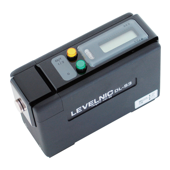
Page 6: Names Of Component Parts
[Names of Component Parts] 0-Call switch 1/2-Call switch-cum-signal output switch Auxiliary bubble tube Display panel Power switch Unit selector switch Mode switch Function selector switch Level base... - Page 7 (10) Signal output jack (11) AC adapter jack (12) Battery case (13) Battery case knob...
-
Page 8: Functions Of Component Parts
[Functions of Component Parts] (1) 0-Call switch Pressing the 0-Call switch resets the indication to zero. The 0-Call switch changes the indication the moment it is released. Operate the switch by pressing it rather leisurely for a second or so. (2) 1/2-Call switch-cum-signal output switch The switch functions as the 1/2-Call switch and also as the signal output switch. - Page 9 (4) Display panel The panel displays inclinations and shows low battery voltage and communication glitches. Inclinations: Indication values can be displayed in either the unit of mm/m or the unit of DEG (º), as selected with the unit selector switch. To distinguish between indications in mm/m and those in DEG (º), 0 of the place to the left of the decimal point is not displayed when indications are produced in DEG (º).
- Page 10 (6) Unit selector switch The switch selects the unit in which indication values are to be displayed, mm/m or DEG (º). The unit of mm/m indicates a difference of elevation per meter in millimeters. The measuring range is ± 5 mm/m. DEG (º) indicates a difference of elevation in an angle.
- Page 11 (10) Signal output jack Through this jack, the measured value currently displayed can be output, together with its unit, in RS-232C conformant signals. The signals can be delivered directly to a computer and printer equipped with an RS-232C input. For details, see Section [External Signal Output]. (11) AC adapter jack This is a jack designed to feed power to the device from outside.
-
Page 12: Variation Of Measuring Range Due To Movement Of Reference Point
[Variation of Measuring Range due to Movement of Reference Point] By operating the 0-Call switch or 1/2-Call switch, zero indication can be produced on a given indication value or the indication value can be halved, thereby allowing the reference point of indication to be moved. - Page 13 When 0-Call and 1/2-Call have not been practiced (The reference point of indication is situated at the zero point of the internal value.) Internal value Reference point of indication Measuring range When the reference point of indication has been moved by +0.1 mm/m due to 0-Call and 1/2-Call (For example, 0-Call was made on +0.1 mm/m;...
-
Page 14: Operation Method
[Operation Method] This is a precision measuring instrument. Exert extreme care in handling it so as not to drop it, hit it against something or otherwise inflict shocks to it. Before using the device, wipe off dirt and oil films thoroughly from the measuring surface of the base, as well as from that of the object to be measured with the device, using a clean piece of glass paper or cloth impregnated with Ligroin or alcohol. - Page 15 When the display panel side (right-hand side as viewed from front) of the device is raised, it indicates an inclination in a positive value, and when that side is lowered, the device shows an inclination in a negative value. Even if an error is currently displayed due to an inclination exceeding the measuring range, it can be known toward which side the device is inclined, because an error on the negative side is preceded by a negative sign.
-
Page 16: Zero-Point Setting
[Zero-Point Setting] This device does not have a zero point of level. The numeric value zero that is first displayed when the device is switched on (internal value) does not necessarily coincide with the zero point of level. Therefore, if a zero point of level is required for some measurement, it will be necessary to set up a zero point of level anew every time the device is switched on. - Page 17 <Functions of 0-Call and 1/2-Call> Since the level works acutely on the gravity of the earth, the zero point of level can be known by the following way of thinking. Suppose there is a slope of angle θ with respect to the horizontal plane. Place on that slope a board with a weight suspended on thread.
-
Page 18: Leveling
[Leveling] Leveling in one direction: (1) Place the device on the object under measurement. Check the position of the bubble in the auxiliary bubble tube, and perform 0-Call, so that the indicator will show zero. (2) Turn the device around 180º, and check to make sure that the bubble in the auxiliary bubble tube stays in the same position. - Page 19 Leveling in two directions (x- and y-directions): (1) Perform leveling in one direction (x-direction, for example) by the method of "Leveling in one direction." (2) Practice leveling in the other direction (y-direction) by the same procedure. (3) When the object under measurement is moved in seeking leveling in one direction, the level in the other direction may be disrupted.
-
Page 20: External Signal Output
[External Signal Output] Indication values can be output together with their units through the signal output jack which is located on the back of the device. Since the signals conform to the RS-232C, they can be connected to a computer and printer that have an RS-232C input interface incorporated. - Page 21 (Symbol denotes a space.) Output in the unit of mm/m Output in the unit of mm/m Output in the unit of mm/m Output in the unit of DEG (º) Output in the unit of DEG (º) Output in the unit of DEG (º) Error output Error output Signal output is basically controlled with CTS.
- Page 22 Note 1. If the CTS terminal turns to Low Level and remains in that status for about three seconds or longer during the transmission of 16 character signals, causing the transmission to be interrupted, E1 will appear on the display panel for about three seconds, and then, the normal operation will be restored.
-
Page 23: Transportation Method
[Transportation Method] Since this is a precision measuring instrument, be careful not to inflict impact, excessive pressure or vibration to the device when carrying it or transporting it. Carrying by human: To carry the device, put it in the carrying case which was supplied with the device. Avoid carrying it laid on its side or turned upside down. -
Page 24: Precautions
[Precautions] Since this device is a precision class measuring instrument, exercise good caution in using it and carrying it, so that no impact or exceedingly large pressure will be applied to its measuring surface or main body. The measuring surface at the bottom of the level base is a particularly critical part for its function. Exert extreme care about rust inhibition. -
Page 25: Specifications
[Specifications] Model DL-S3 Measuring range ±5.00 mm/m, ±0.286º Minimum reading 0.001 mm/m, 0.0001º (*1) 0.01 mm/m, 0.001º Operating temperature range 0 – 40°C Reading accuracy [17 – 23°C] (*2) ±0.85%rdg (0 – ±2 mm/m, 0 – ±0.115º) ±1.0%rdg (±2 – ±5 mm/m, 0.115 – ±0.286º) [0 –... - Page 26 NIIGATA SEIKI CO., LTD 1-22-17 HAYASHICHO SANJO-CITY, NIIGATA PREF., JAPAN TEL 81-25-33-5500 FAX 81-256-33-5550 URL http://www.sokuteikougu.com...