Advertisement
Quick Links
D D IGITAL BORE GAUGE
Thank you for purchasing the Digital Bore Gauge.
Please read this manual thoroughly before use for proper operation.
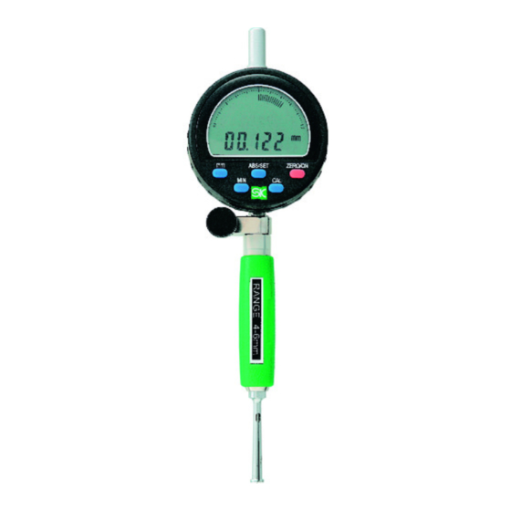
■ PART IDENTIFICATION
Gauge
(Digital Indicator)
※2
LCD Display
[ ABS/SET ]
Button
※1
[ ZERO/ON ]
[ MIN ] Button
Button
Clamp Screw
[ CAL ] Button
Cap
Probe Tip
Handle
×4
※1:Not Used
※2:"0.01" indicates the resolution of
Probe Tip
the display's digital bar graph.
The bar graph display will
Measurement
change with each 0.01mm
Head
change in the measured value.
NOTICE
●This is a precision instrument, handle with care.
●Do not disassemble or modify.
●Keep instrument away from water and oil.
●Use only with supplied Probe Tips and Probe Needle.
●Keep instrument away from direct sunlight and high temperatures such as
in a car, or near a stove or heat source.
●After use, remove any dirt or cutting chips and apply rust preventative oil
to Probe Tip and Probe Needle. When not in use store in supplied storage
case.
●This product is for measuring inside diameter; use only as directed.
Improper use may cause accident or injury.
●Avoid using in high electric fields, such as near fluorescent lights or
switching power supplies. Electrical interference may cause incorrect
readings.
■ ASSEMBLY
①Loosen the Clamp Screw and insert the Digital
Indicator into the gauge body. Tighten the
Clamp Screw to secure. ( Figure A )
②Insert the Probe Needle into the Probe Tip and
screw onto the end of the Handle. Tighten as
shown using the Spanner to secure. ( Figure B,C )
※Select Probe Tip to match the desired
measurement range.
※After attaching, press the [ ZERO/ON ] Button on
the Digital Indicator to turn on power. Confirm
that the displayed reading changes by gently
squeezing the measurement head.
If necessary, adjust the depth that the Digital
Indicator is inserted into the gauge body.
Instruction Manual
■ SPECIFICATIONS
*Including supplied Digital Gauge
※Not including quantization error ( ±1 count )
Model No.
(mm)
Measuring Range
(mm)
Resolution
*
(μm)
※
Wide range accuracy
*
(μm)
※
Adjacent error
*
(μm)
※
Repeatability
(mm)
Single Stroke Range
(mm)
( hr)
Auto Off Delay
( g )
Weight
ACCESSORIES
● Probe Tip ・・・・・・ 4.0 - 4.6mm, 4.5 - 5.1mm
5.0 - 5.6mm, 5.5 - 6.1mm ( 4pcs )
● Probe Needle・・・
(※Note: When purchased, Probe Needle
1 x
is inserted into Measurement Head)
● Spanner ・・・・・・・
1 x
● Battery・・・・・・・・・ CR2032 Lithium cell,
Probe
Spanner
■ INSERTING・REPLACING BATTERY
Needle
Pull out the case
from the two side
Battery
(CR2032)
edges to remove.
Insert battery with
(
+
)
side facing down.
Battery
NOTICE
Case
Use only CR2032 type
lithium button cell.
■AUTO OFF DELAY
①Press and hold the [ ZERO/ON ] Button to turn
power OFF.
②Press and hold [ ABS/SET ] and [ ZERO/ON ]
Buttons at the same time.
③When 「-----」 is displayed, ❶release the [ ZERO/ON ]
Button, ❷then release the [ ABS/SET ] Button in
that sequence.
④The Auto Off Delay time will be displayed. Press
[ ABS/SET ] to change.
※Each press of the [ ABS/SET ] Button will change the
delay by 1/2 hr. ( 30 min. ) from 0 to 6 hr.
⑤Press [ ZERO/ON ] when done and display will return
to the measurement screen.
※Once set, the delay time is saved even when power is OFF.
ABS/SET
ZERO/ON
MIN
CAL
Probe
Needle
Clamp
Probe
Screw
Tip
(Fig.A)
(Fig.B)
■ MEASUREMENT
For accurate measurements, follow the procedure described below.
Model No.:WCDI-6D
①In cross section perpendicular to the axis of the bore, as shown in Figure 1, position the gauge along diameter ⓐ. This is the
maximum distance, and at this point the Indicator will read the maximum value. The Measurement Head will automatically move to
diameter ⓐ when inserted.
②In cross section parallel to the axis of the bore through diameter ⓐ, position the indicator to minimize the distance ⓑ. ( Figure 2 )
In this position the Indicator will read the minimum value. This position must be manually determined by pivoting the Gauge as
shown in Figure 3 while watching the Indicator to find the minimum value.
WCDI-6D
4-6
a
0.002
10
5
3
0.6
(Fig. 1)
0 〜 6.0
■OPERATION
255
①Before use, please make sure the Measurement Head components are not loose and tighten if necessary.
②Clean the Measurement Head and the ID of a Ring Gauge Standard using parts cleaner or cleaning solution.
③Press the [ ZERO/ON ] Button to turn on power. ※ A long press to the [ ZERO/ON ] Button will turn power off.
ABSOLUTE MODE ( ABS )
①Turn on power. If the "
1 x ( for test )
②Adjust the "SET" value of the Bore Gauge to match the ID of the Ring Gauge Standard. Press and hold the [ ABS/SET ] Button until
"SET" blinks on the display.
③Continue holding the [ ABS/SET ] Button and the display character to the left will blink. Use a short press of the [ ABS/SET ] Button to
change the value, and a long press to change the character being modified. Repeat this process to enter the dimension of the Ring
Gauge Standard on the LCD display. ( Figure 4 )
④When the value is entered the flashing position will return to "SET". A short
press of the [ ABS/SET ] Button to turn off the flashing.
⑤Insert the Measurement Head into the Ring Gauge Standard and press the
[ MIN ] Button to put the Indicator into minimum-mode. Slowly pivot the
gauge ( Figure 3 ) to display the minimum value.
⑥Remove the gauge from the Ring Gauge and press the [ CAL ] Button until
"OK" is displayed.
Preparation for measurement is now complete.
⑦Put the gauge into the workpiece to be measured, and pivot the gauge
slowly. ( Figure 3 ) The LCD will display the measured value. ( Figure 5 )
※Press the [ ON/ZERO ] Button momentarily to reset display in preparation
to measure the next workpiece.
COMPARATIVE MEASUREMENTS
①Turn on power. If "
press the [ MIN ] Button to turn off. If "ABS" is displayed press the
[ ABS/SET ] Button to turn off.
②Insert the Measurement Head into the Ring Gauge Standard and press
[ MIN ] Button to put the Indicator into minimum-mode. Slowly pivot the
gauge ( Figure 3 ) to display the minimum value.
③Remove the gauge from the Ring Gauge and press the [ CAL ] Button until
"OK" is displayed.
Preparation for measurement is now complete.
④Put the gauge into the workpiece to be measured, and pivot the gauge
Spanner
slowly. ( Figure 3 ) The LCD will display the difference between the
measured workpiece and the calibration standard. ( Figure 6 )
※Press the [ ON/ZERO ] Button momentarily to reset display in preparation
to measure the next workpiece.
■ TROUBLESHOOTING
Handle
ERROR
ATTACH
Probe
●LCD does not display
Tip
●Displayed value is unstable
(Fig.C)
●Display is not clear
b
(Fig. 2)
(Fig. 3)
※Measure absolute dimension of workpiece
" or "
" symbols are displayed on the LCD, press the [ MIN ] Button to turn off.
※Difference between workpiece and reference
" or "
" symbols are displayed on the LCD,
※If problem persists, or if you have any
CORRECTIVE ACTION
questions, please contact distributor.
●Cycle power by removing and
※Please note, manufacturer is unable to
replacing battery.
respond to inquires or provide service
●Replace battery with new one.
directly. Please contact distributor.
Example
ABS
ABS
mm
Ring Gauge
ABS/SET
ZERO/ON
Standard
Set to match
MIN
CAL
(Fig. 4)
ABS
ABS
mm
Work-
piece
ABS/SET
ZERO/ON
Workpiece I.D. value
MIN
CAL
(Fig. 5)
ABS
mm
Work-
piece
ABS/SET
ZERO/ON
Diff. between Work-
MIN
CAL
piece and Reference
(Fig. 6)
Niigata Seiki Co., Ltd.
5-3-14, Tsukanome, Sanjo, Niigata, Japan, 955-0055
Tel. : +81-256-33-5522 Fax. : +81-256-33-5518
MAIL intl.sales@niigataseiki.co.jp
URL
http://www.niigataseiki.co.jp
Advertisement

Related Manuals for Niigata seiki WCDI-6D


Summary of Contents for Niigata seiki WCDI-6D
- Page 1 ERROR CORRECTIVE ACTION ATTACH Probe questions, please contact distributor. Niigata Seiki Co., Ltd. squeezing the measurement head. ●LCD does not display ●Cycle power by removing and ※Please note, manufacturer is unable to ●Displayed value is unstable...
- Page 2 * : 付属のデジタルインジケータ (指示器) を含めた値です。 この直径 b は、手動で求めます。 シリンダゲージを (図3) のように振り、指示器が最小値を示す点を探してください。 ※ 量子化誤差 (±1カウン ト) 含まず 指示器 品 番 WCDI-6D (デジタルインジケータ) 測 定 範 囲 (mm) a LCD表示部 b ※2 目 量...