Table of Contents
Advertisement
Quick Links
Precision Electronic Level
≪
≫
Compact Digital Level
DL-m3
LEVELNIC Owners Manual
Thank you for purchasing Niigata Seiki LEVELNIC.
Please read this manual thoroughly before use to insure proper operation
and a long service life.
[ CONTENTS ]
Introduction ・・・・・・・・・・・・・・・・・・・・・・・・・・・・・・・・・・・・ 2
Features ・・・・・・・・・・・・・・・・・・・・・・・・・・・・・・・・・・・・・・・・ 2
Part Identification・Function ・・・・・・・・・・・・・・・・・・・・・・ 3
Measurement Range and Zero Point ・・・・・・・・・・・・・・ 7
How to Use ・・・・・・・・・・・・・・・・・・・・・・・・・・・・・・・・・・・・・ 9
Zero-Point Setting ・・・・・・・・・・・・・・・・・・・・・・・・・・・・・・・ 11
Leveling a Surface ・・・・・・・・・・・・・・・・・・・・・・・・・・・・・・・ 13
Shipping ・・・・・・・・・・・・・・・・・・・・・・・・・・・・・・・・・・・・・・・・ 17
Notices ・・・・・・・・・・・・・・・・・・・・・・・・・・・・・・・・・・・・・・・・・ 18
Specifications ・・・・・・・・・・・・・・・・・・・・・・・・・・・・・・・・・・・ 19
-1-
Advertisement
Table of Contents

Related Manuals for Niigata seiki LEVELNIC


Summary of Contents for Niigata seiki LEVELNIC
-
Page 1: Table Of Contents
≪ ≫ Compact Digital Level DL-m3 LEVELNIC Owners Manual Thank you for purchasing Niigata Seiki LEVELNIC. Please read this manual thoroughly before use to insure proper operation and a long service life. [ CONTENTS ] Introduction ・・・・・・・・・・・・・・・・・・・・・・・・・・・・・・・・・・・・ 2 Features ・・・・・・・・・・・・・・・・・・・・・・・・・・・・・・・・・・・・・・・・ 2... -
Page 2: Introduction
[ INTRODUCTION ] This high precision microcomputer controlled level measures angle by measuring the displacement of a pendulum. Displacement is converted to an electronic signal and is displayed as mm/m of inclination on the digital display. [ FEATURES ] Capacitive sensor for high sensitivity and stable output. ◎... -
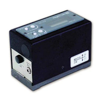
Page 3: Part Identification・Function
[ PART IDENTIFICATION ・ FUNCTION ] Display (1) 0-Cal Button (2) Power Switch (3) 1/2-Cal / Output Signal Button (4) Function Select Switch (5) Battery Cover Screw (6) Battery Cover (7) Data Out Jack (8) Base (9)... - Page 4 (1) Display Display shows angle measurements, battery status, and communication status. Angle The angle is displayed in units of mm/m. If the angle exceeds the measurement range, an error message is displayed. For a positive out-of-range error, "EEE" is displayed, and for a negative out-of- range error, "-EEE"...
- Page 5 (4) 1/2-Cal / Output Signal Button Button function is set by the Function Select Switch to work as either 1/2- Cal Button, or Output Signal Button. 1/2-Cal Button Press the 1/2-Cal button to divide the displayed reading by 2. Value is changed when the 1/2-Cal button is released. Button requires deliberate press of about 1 sec.
- Page 6 (6) Battery Cover Screw When replacing battery, turn counter clockwise to remove. (7) Battery Cover When replacing the cover, make sure the tab is inserted into the slot at the bottom of the compartment. Slot (8) Data Out Jack RS-232C port for sending the displayed value and units to a remote device for recording or display.
-
Page 7: Measurement Range And Zero Point
[ Measurement Range and Zero-Point ] The instrument can be set to display a reference point of "0" at any angle using the 0- Cal and 1/2-Cal buttons. However, the measuring range of the instrument is limited by the range of the internal variable measured by the device. - Page 8 Cal, 1/2-Cal operations have not been performed. ◎ (Zero reference point for displayed value is same as internal reference.) Internal Zero Display Zero→ Measurement Range ◎ Reference point moved 1 mm/m using the 0-Cal, 1/2-Cal operations. (For example, initial reading was 1 mm/m when 0-Cal is performed, or 2 mm/m before 1/2-Cal is performed.) Internal Zero Display Zero→...
-
Page 9: How To Use
[ HOW TO USE ] This is a precision instrument. Please handle with care and avoid any shock or mishandling. Before use, wipe the instrument base and the surface to be measured using a soft cloth or lens cloth moistened with mineral spirits or alcohol to remove any grease and contamination. - Page 10 When viewed from the front (with the display on the right side,) if the right side is elevated the angle reading will be an increasing positive number. If the angle is out of range an error message will be displayed. For negative angles, a "‒"...
-
Page 11: Zero-Point Setting
[ ZERO-POINT SETTING ] The instrument does not have a preset absolute zero-point. When first turned on, a reading of zero ( the internal value ) will not necessarily indicate that the gauge is at true horizontal position. If a zero-point is required it must be set each time the instrument is switched on. - Page 12 ≪ 0-Cal, 1/2-Cal Operation ≫ The zero-point reference is set without an absolute reference by using the direction of Earth's gravity as a reference. This can be understood from the following procedure. Suppose a slope having an angle θ with respect to the horizontal plane. Place on that slope a board with a weight suspended on thread.
-
Page 13: Leveling A Surface
[ LEVELING A SURFACE ] Leveling in one direction. (1) Place the instrument on the surface, and once the display has stabilized press the 0-Cal Button. (2 ) Rotate the instrument 180° in the same location on the surface, and once the display has stabilized press the 1/2-Cal Button. - Page 14 Leveling in two directions (X、Y direction) (1) For one direction (for example the X-direction,) follow the above procedure for “Leveling in one direction.” (2) Repeat the procedure for the other direction (the Y-direction.) (3) When adjusting in one direction, it is possible that the perpendicular direction will be affected and no longer level.
-
Page 15: Output Signal ・・・・・・・・・・・・・・・・・・・・・・・・・・・・・・・・・・・ 1
[ Output Signal ] The measurement value and units can be read off the Data Out Jack. The signal is RS-232 compatible so can be connected to any computer or printer with an RS-232 port available. Use an audio type mini-plug for connecting cable to Data Out Jack. (1)... -
Page 16: Timing Chart
Signal output is controlled by the CTS signal. CTS tells the system when to transmit, or not to transmit data. If the Function Select Switch is set to “1/2” For CTS level “high”, measurement data is sent on TD with each data update.. For CTS level “low”, or not connected, measurement data is not sent. -
Page 17: Shipping
[ SHIPPING ] This is a precision instrument; when carried or shipped, care must be taken to avoid damage. Please be careful not so subject instrument to shock, vibration, or excessive forces when shipped. Hand Carrying Always transport in supplied case. Transport in upright position and not on side or upside down. -
Page 18: Notices
[ NOTICES ] This is a precision instrument, handle with care. While in use and during transport protect from excessive shock, vibration, or excessive force to the main body or to the measuring surface. The measuring base is critical component for accurate measurements, use care to protect from corrosion. -
Page 19: Specifications
100 (L) × 50 (W) mm Weight 0.88kg Accessories 9V Battery Storage Case Owner's Manual % rdg is "percentage of reading" (※1) Some variation depending on usage conditions. (※2) NIIGATA SEIKI CO., LTD 6-15-22, Tsukanome, Sanjo-city, Niigata 955-0055 JAPAN TEL: 0256-31-5670 -19-...