Advertisement
Quick Links
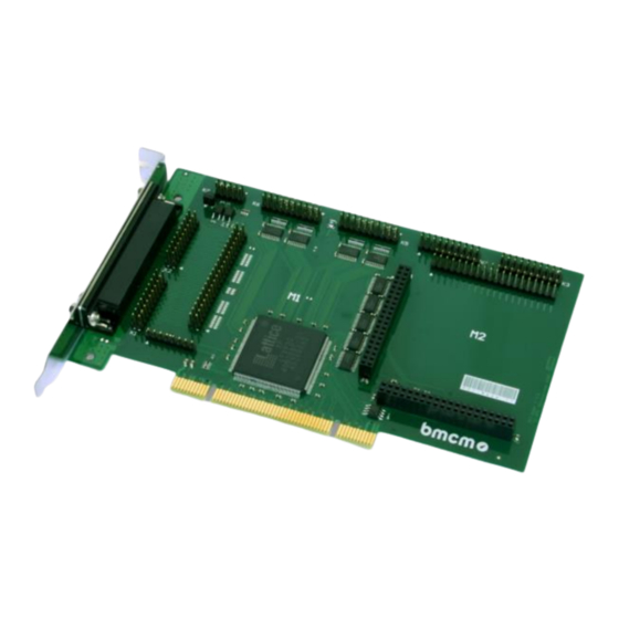
PCI-BASEII
Data Acquisition and Control Card (PCI)
Measurement & Control.
Multifunctional.
The PCI-BASEII is a multifunctional data
acquisition and control card for stationary
applications. Its modular structure guarantees
individual and flexible adjustment to a
measuring task. The short latency of the PCI
interface makes the card especially attractive
for controlling tasks.
Modular Concept. Optimize
Price-Performance-Ratio.
Perfectly adapted to the respective
measurement application, data acquisition
modules can be selected to equip the two
module slots of the
PCI-BASEII. It is the customer who decides
about performance and price of his DAQ
system!
Modules: MADDA. MDA. MCAN.
What Would you Like?
A great variety of analog plug-on modules is
available differing in the number of inputs and
outputs, resolution and sampling rate. If a
MADDA module e.g. is combined with a CAN
module, analog measurements and via the
Functional diagram
CAN interface are possible. Analog, digital,
and CAN channels are sampled time-
synchronously.
32 Digital Inputs/Outputs.
3 Counters.
The PCI-BASEII features 32 digital lines, which
means that the base board is a digital I/O card
itself. The direction of the two 16-bit ports is
set via software. 3 counters accessible via any
digital inputs allow the acquisition of counting
pulses or the connection of incremental
encoders.
PCI. Well Fitted in the PC.
The PCI-BASEII is installed in a free PCI slot
and is supplied by the PC – all this without
annoying cables. The PC housing provides
optimum protection against interferences. Due
to Plug&Play, the card is recognized
automatically by the PC making installation a
lot easier.
Windows
. That's it.
®
The PCI-BASEII can be used on Windows
XP/7/8/10. The entire software for installation
and programming of the multifunction card is
included for free.
NextView
. Try for Free.
®
The DAQ card is supported by NextView
software for data acquisition and analysis. A
fully functional 14-day trial is included with
delivery to directly test the functionality of the
PCI-BASEII.
®
, the
®
Advertisement

Related Manuals for bmcm PCI-BASEII


Summary of Contents for bmcm PCI-BASEII
- Page 1 PCI. Well Fitted in the PC. module slots of the PCI-BASEII. It is the customer who decides The PCI-BASEII is installed in a free PCI slot about performance and price of his DAQ and is supplied by the PC – all this without system! annoying cables.
-
Page 2: Start-Up Procedure
PC, shut down and turn off the PC and open the PC housing. After removing a blank bracket, plug the PCI-BASEII in a free PCI slot of the off-state PC. Boot up the PC and start the Plug&Play installation. The power supply of the card is provided via the PCI bus. - Page 3 PCI-BASEII 2 Module Concept Overview The following PCB view shows the module slots M1 and M2, which can be assembled with analog data acquisition modules (MADDA series), analog control modules (MADDA/MDA series) or a CAN interface module (MCAN). They can be used in any combination.
- Page 4 Lead Connections from M2 to D-Sub37 By closing the solder bridges PL400-403 and PL406-409 and opening PL 410-414 on the bottom side of the PCI-BASEII board, the first four channels of an analog module (MADDA or MDA series) mounted on slot M2 are led to the free pins of the 37-pin D-Sub female to be available from the outside.
- Page 5 PCI-BASEII • Channels of MCAN modules cannot be reached in that way at the D-Sub37 female connector! • The corresponding ground pin for the analog channels of the M2 module slot is exclusively available at pin 17 of the D-Sub 37.
-
Page 6: Digital Channels
PCI-BASEII 3 Digital Channels The PCI-BASEII features two digital ports with 16 inputs or outputs each. The lines are bidirectional and set in groups of eight. The connections are designed as two 20-way pin connectors (male) on the board (see Figure 1, p.3). - Page 7 5V Auxiliary Voltage The PCI-BASEII provides an auxiliary voltage (e.g. for sensor supply) at pin 17, 18 of the pin connector K5. The 5V DC output (100mA) is protected by a fuse (multifuse). In case of overload, it is sufficient to interrupt the power supply (turn off PC or disconnect the consumer load).
-
Page 8: Interfacing Examples
PCI-BASEII 4 Interfacing Examples In the following examples, the signal is always connected at port A, line 1 (pin 11). Before, however, the relating digital port must have been switched to input (see chapter 4.1) or output (see chapter 4.2). - Page 9 PCI-BASEII 4.1.4 Connecting a Counter / Incremental Encoder The connection of "Signal A", "Signal B" and "Reset" is possible at any digital line. Make sure to configure the relating digital lines as input and to assign them to the counter.
- Page 10 PC slot. With the ZUKA16, the channels provided by module slot M2 (see chapter 2.2) and the digital lines of the PCI-BASEII (see chapter 3) can be reached externally. The line of the flat ribbon cable leading to pin 1 of the D-Sub37 is colored.
- Page 11 When removing the modules, only use blunt tools! Exposing the card to strong vibrations requires additional protection of the modules. • If connecting internal ribbon cables to the PCI-BASEII, please make sure the modules are well ventilated to prevent excess heating. Also observe the temperature ranges of the PC. •...
-
Page 12: Technical Data
Available accessories: connecting cables ZUKA37SB, ZUKA37SS, connector panels ZU37BB/-CB/-CO, current shunt ZU-CS250R, modules of the series MADDA/MDA/MCAN 2 years from date of purchase at bmcm, claims for damages resulting from improper use excluded Warranty: • Software LIBAD4 SDK for C/C++ programming on Windows...
Need help?
Do you have a question about the PCI-BASEII and is the answer not in the manual?
Questions and answers