Advertisement
Quick Links
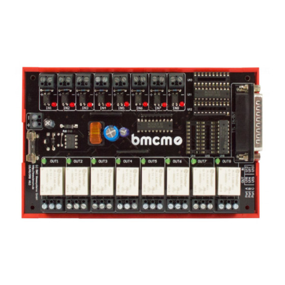
OR8/R8
Optocoupler/Relay cards
Connect digital signals.
Quite simple.
The optocoupler and relay boards OR8 and R8
are ideal to monitor and control digital states.
The digital inputs and outputs can be
connected directly via a screw-clamp
connection.
8 optocoupler inputs (OR8).
8 relay outputs (OR8, R8).
The eight optocouplers on the OR8 convert
digital inputs in the voltage range of 5..30V into
TTL signals. Via relays, the OR8 and R8 switch
eight control lines (TTL) with up to 6A.
Clearly safe.
Due to the galvanic isolation of the channels
from each other and from the data acquisition
and control system, the whole system is
perfectly protected.
Current states.
Eight LEDs each dedicated to the inputs and
outputs signalize if a channel is high or low.
Funktionsschaltbild
Well supplied.
The R8 is operated with 5V. The OR8 is
powered with 9-40V but can also be configured
to 5V supply. The supply voltage is also
connected via screw-clamp terminals.
DIN rail mounting.
The optocoupler and relay boards are suitable
for DIN rail mounting. A DIN rail carrier (ZU-
EW) with bracket is already included with the
delivery of the OR8. It can be ordered as
accessory for the R8.
Compatibility.
Particularly simple is the connection to the
digital I/O interface USB-PIO as only a 25-pin
D-Sub extension cable is needed for
connecting.
Advertisement

Related Manuals for bmcm OR8


Summary of Contents for bmcm OR8
- Page 1 Well supplied. The digital inputs and outputs can be The R8 is operated with 5V. The OR8 is connected directly via a screw-clamp powered with 9-40V but can also be configured connection.
- Page 2 • Please carefully observe the polarity! Only apply voltages within the adjusted range! • It is very important to turn the direction of the port packages to input, when connecting the OR8 to the USB-PIO! Otherwise the cards might be damaged! Relays (OR8, R8) The responding of the relays OUT1..OUT8 depends on the applied...
- Page 3 B (bit 0..7) = inputs (optocouplers 1..8) Pin assignment and direction of the digital lines at the D-Sub25 male connector of the OR8 can be defined by the user. This is done by two ICs plugged on the corresponding sockets U10-U12 (for optocoupler inputs) and U14-U16 (for relay outputs).
- Page 4 7 OUT7 channel 8 OUT8 If using a digital I/O system from bmcm (e.g. USB-PIO) connected 1:1 to the R8, port A of the USB- PIO must be set to input. 2 Important notes for using the OR8/R8 •...
Need help?
Do you have a question about the OR8 and is the answer not in the manual?
Questions and answers