Advertisement
Quick Links
®
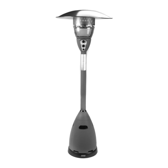
Patio Heater & Light
Model 5040B740
Model 5040B750
INSTRUCTIONS FOR USE
Patent # 6,422,232
Patent # 6,499,480
Patent # US D451,988 S
© 2003 The Coleman Company, Inc.
www.coleman.com
IMPORTANT
Read this manual carefully before assembling,
using or servicing this heater. Keep this manual for
future reference. If you have questions about
assembly, operation, servicing or repair of this
heater, please call Coleman at 1-800-835-3278 or
TDD: 316-832-8707.
In Canada call 1-800-387-6161.
®
®
1AS 9-96 & CSA International
Requirement 5.90 U.S.
Advertisement

Subscribe to Our Youtube Channel
Related Manuals for Coleman 5040B740


Summary of Contents for Coleman 5040B740
- Page 1 Keep this manual for future reference. If you have questions about assembly, operation, servicing or repair of this heater, please call Coleman at 1-800-835-3278 or TDD: 316-832-8707. In Canada call 1-800-387-6161. 1AS 9-96 & CSA International Requirement 5.90 U.S.
-
Page 2: For Your Safety
If you need assistance or heater information such as an instruction manual or labels, contact the Coleman Co., Inc. • Keep solid combustibles, such as building materials, paper or card- board, a safe distance away from the heater as recommended by the instructions. -
Page 3: General Safety Information
• During set up, check all connections and fittings for leaks using soapy water. Never use a flame. • Use as a heating appliance only. Never alter in any way or use with any device or part not expressly approved by Coleman. • Check entire hose at least annually. Tools Required Phillips screwdriver and 7/16”... - Page 4 Assembly Step 1 (continued) Attach Post Base to Cylinder Cover Pieces loosely with seven Large Screws. Step 2 Identify Center Rear Support Bracket. It has six holes, various sizes. Place Center Rear Support Bracket in place over the center screw. Step 2 large screw loosely through Cover Pieces into base of Center Rear...
- Page 5 Assembly continued. Step 3 (continued) Attach the second Side Support Attach one large screw loosely Bracket loosely with Hex Nut at at base of the second Side top. Support Bracket. 1 Req’d Hex Nut Step 4 Set cylinder cover assembly on top of heater base.
- Page 6 Assembly continued. Step 6 Install post onto post base. Decal on post should face front large screws. of heater (see photo on front cover). Step 7 Load cover onto post. (For models without a table, skip to Step 12) Step 8 Insert table supports into the receptors located in the underside of the table frame.
- Page 7 Assembly continued. Step 12 Insert studs into screen cover. 3 Req’d Brass Reflector Studs Step 13 Load head assembly by inserting hose into post. Insert head assembly into post. Attach head assembly to post, Control knob should be above and loosely install three screws. decal on post.
- Page 8 Assembly continued. Step 15 (continued) Attach regulator to tank. Complete attachment. Screw regulator onto hose. Do not cross-thread. Install tank. Tighten Securely. Install tank.
-
Page 9: Leak Check
• Apply several drops of solution where hose attaches to regulator. • Apply several drops of solution where regulator connects to Cylinder. • Make sure all Patio Heater & Light valves are OFF. • Turn Cylinder Valve ON. If bubbles appear at any connection, there is a leak. -
Page 10: Operation
Mantles continued. Attach second mantle. Illustration below shows proper assembly of both mantles. Light bottom of mantles evenly. Burn until nothing but white ash remains. Once mantle has been burned it’s very fragile. Be careful not to touch it with a finger or match. Install glass panels. Battery Installation for HEATER Unscrew igniter button to reveal battery compartment. - Page 11 Operation continued. Lighting Instructions for HEATER 3. Pilot Light will ignite and be visible through Pilot Viewing Port (flame may be difficult to see in broad daylight). Continue to push Heater Control Knob in for 30 to 60 seconds after pilot is on, then release knob.
-
Page 12: Maintenance
Operation continued. Match Lighting Instructions for LIGHT 1. Turn cylinder valve on. 3. Place a lighted match near mantle, then push in and rotate Light Control Knob to the ON position. Immediately light second mantle with match. Note: If BOTH mantles are not lighted within 5 seconds, turn Light control knob to OFF position. -
Page 13: Troubleshooting
Troubleshooting Problem Possible Cause Pilot won’t light Cylinder valve is closed Blockage in orifice or pilot tube Air in gas line Low gas pressure with Cylinder Valve fully open Igniter fails Heater control knob not fully depressed in pilot position when lighting pilot No spark at burner electrode Pilot won’t stay lit... - Page 14 Replacement Parts - Patio Heater & Light Part No. Description 5040-1541 Reflector including hardware 5040B5441 Pilot Assembly (Including tip switch) 5040-1221 Glass and Frame 5040-1461 Heater Knob 5040-1511 Lantern Knob 5040-1451 E.I. Button 5040-3101 Electrode 5040-5571 Lantern & Heater Valve Assembly...
-
Page 15: Replacement Parts - Table
Replacement Parts - Table Parts List No. Part No. Description 5040-1081 Table Assembly (Painted, Copper Vein) 5040-1021 Table Assembly (Stainless) 5040-0881 Table Support & Hardware (Painted, Copper Vein) 5040-0891 Table Support & Hardware (Painted, Silver) 5040-0181 Clamp (Painted, Copper Vein) 5040-0191 Clamp (Painted, Silver) - Page 16 Warranty Coleman will repair or replace, at its option, this product or any component found to be defective in materials or workmanship within seven years of the original retail purchase. This warranty is valid for the original retail purchaser from the date of initial retail purchase and is not transferrable.
Need help?
Do you have a question about the 5040B740 and is the answer not in the manual?
Questions and answers