Table of Contents
Advertisement
Quick Links
Advertisement
Table of Contents

Subscribe to Our Youtube Channel
Related Manuals for AMI ATX-H310A


Summary of Contents for AMI ATX-H310A
- Page 1 ATX-H310A...
- Page 2 The original manufacturer reserves the right to make changes in the product design without notice to its users. Acknowledgments All other products’ name or trademarks are properties of their respective owners. • AMI is a trademark of American Megatrends Inc. • Intel , Core™ are trademarks of Intel Corporation.
-
Page 3: Table Of Contents
Contents Chapter 1 Product overview Package contents ................. 1-1 Features ..................1-1 1.3 Specifications ................1-2 Chapter 2 Motherboard information Before you proceed ..............2-1 Motherboard layout ..............2-2 Screw size ..................2-4 2.3.1 Component side .............. 2-4 2.3.2 Solder side ..............2-5 Central Processing Unit (CPU) ........... - Page 4 Chipset menu ................3-15 3.4.1 System Agent (SA) Configuration ......... 3-15 3.4.2 PCH-IO Configuration ........... 3-15 Security menu ................3-16 3.5.1 Administrator Password ..........3-16 3.5.2 User Password .............. 3-16 Boot menu .................. 3-17 3.6.1 Boot Configuration ............3-17 3.6.2 FIXED BOOT ORDER Priorities ........3-17 Save &...
-
Page 5: Chapter 1 Product Overview
Chapter 1 Product overview Package contents Check your industrial motherboard package for the following items. 1 x Industrial Motherboard 1 x SATA Cable 1 x I/O Shield 1 x COM port cable If any of the above items is damaged or missing, contact your distributor or sales representative immediately. -
Page 6: Specifications
® 1 x Intel i211AT Giga LAN ® 2 x RJ45 ports BIOS 1 x 128Mbit Flash ROM, AMI BIOS Wake on LAN/PXE Yes (WOL / PXE) Watchdog Timer 1~255 steps by software program H/W Monitor Temperature Monitor on CPU/Chassis Voltage Monitor on Vcore/5V/3.3V/12V... - Page 7 DISPLAY Chipset Intel Graphics Media Accelerator ® DisplayPort Up to 4096 x 2160 @ 24 Hz / 3840 x 2160 @ 60 Hz, with Digital Audio HDMI™ Up to 4096 x 2160 @ 30 Hz Up to 1920 x 1200 @ 60 Hz (via IT6516B) Back I/O ports Audio 3 x Audio Jack: Line-in, Mic-in, Line-out...
- Page 8 ATX-H310A...
-
Page 9: Chapter 2 Motherboard Information
Chapter 2 Motherboard information Before you proceed Take note of the following precautions before you install motherboard components or change any motherboard settings. CAUTION! • Unplug the power cord from the wall socket before touching any component. • Before handling components, use a grounded wrist strap or touch a safely grounded object or a metal object, such as the power supply case, to avoid damaging them due to static electricity. -
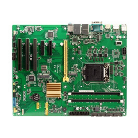
Page 10: Motherboard Layout
Intel ® i211AT LAN2_USB3_56 CHA_FAN1 Intel ® PHY i219V 2280 2242 AUDIO Place this side M2_SSD_LED1 towards the rear PCIEX16_1 of the chassis ATX-H310A 128Mb BIOS Intel ® H310 Super PCIEX4_1 SPI_1 SATA6G_1 SATA6G_2 SIM1 PCIEX4_2 SATA6G_3 PCI1 1083 PCI2... - Page 11 Connectors/Jumpers/Slots Page USB2.0 port (USB20_9) 2-25 ATX power connectors (24-pin EATX_PWR1, 8-pin EATX_PWR2) 2-19 CPU and chassis fan headers (4-pin CPU_FAN1, 4-pin CHA_FAN1~2) 2-20 Intel LGA1151 CPU socket ® M.2 M-Key slot 2-24 DDR4 DIMM slots 2-10 COM Port headers (10-1 pin COM2~6) 2-23 BIOS programmable header (8-pin SPI_1) 2-19...
-
Page 12: Screw Size
243.84 240.28 228.07 232.96 222.25 218.97 214.74 211.06 199.24 190.63 179.94 174.37 173.61 165.23 156.08 147.07 137.03 129.29 126.81 77.22 79.25 77.04 48.09 49.59 42.77 22.11 45.45 16.68 41.28 12.04 31.20 11.84 10.91 19.59 10.49 7.06 5.85 0.00 35.52 ATX-H310A... -
Page 13: Solder Side
2.3.2 Solder side 243.84 237.49 237.49 195.23 165.10 165.10 164.31 151.99 144.81 126.81 108.81 89.31 51.69 33.02 10.16 0.00 Chapter 2: Motherboard information... -
Page 14: Central Processing Unit (Cpu)
Return Merchandise Authorization (RMA) requests only if the motherboard comes with the cap on the LGA1151 socket. • The product warranty does not cover damage to the socket contacts resulting from incorrect CPU installation/removal, or misplacement/loss/ incorrect removal of the PnP cap. ATX-H310A... -
Page 15: Installing The Cpu
2.4.1 Installing the CPU CAUTION! Ensure that you install the correct CPU designed for LGA 1151 only. DO NOT install a CPU designed for LGA1155 and LGA1156 sockets on the LGA1151 socket. Chapter 2: Motherboard information... -
Page 16: Cpu Heatsink And Fan Assembly Installation
2.4.2 CPU heatsink and fan assembly installation CAUTION! Apply the Thermal Interface Material to the CPU heatsink and CPU before you install the heatsink and fan if necessary. To install the CPU heatsink and fan assembly ATX-H310A... - Page 17 To uninstall the CPU heatsink and fan assembly Chapter 2: Motherboard information...
-
Page 18: System Memory
(DIMM) sockets. A DDR4 module is notched differently from a DDR, DDR2, or DDR3 module. DO NOT install a DDR, DDR2, or DDR3 memory module to the DDR4 slot. According to Intel CPU spec, DIMM voltage below 1.2 V is recommended to protect the ® CPU. 2.5.1 Installing a DIMM ATX-H310A 2-10... - Page 19 To remove a DIMM Chapter 2: Motherboard information 2-11...
-
Page 20: Jumpers/Slots
CLRTC jumper default position. Removing the cap will cause system boot failure! NOTE: If the steps above do not help, remove the onboard battery and move the jumper again to clear the CMOS RTC RAM data. After clearing the CMOS, reinstall the battery. ATX-H310A 2-12... - Page 21 COM1 RS422/RS485 terminator (2-pin J1~4) RS232 RS485/RS422 with terminator (Default) AT/ATX Mode selection (2-pin ATX_AT) ATX_AT ATX mode AT mode (Default) Pins 1-2 (Default) ATX mode AT mode NOTE: Jumper setting of ATX_AT should be consistent with the setting of Power Mode in BIOS.
- Page 22 By default, the pin labeled “Chassis Signal” and “Ground” are shorted with a jumper cap. Remove the jumper caps only when you intend to use the chassis intrusion detection feature. CHASSIS PIN1 COM1 Ring/+5V/+12V selector (6-pin COM1_V1) COM1_V1 +12V Ring (Default) Setting Pins +12V Ring (Default) ATX-H310A 2-14...
- Page 23 Intel ME Jumper (3-pin DIS_ME) ® This jumper allows you to force the Intel Management Engine (ME) to boot ® from recovery mode when ME becomes corrupted. DIS_ME ME Enable ME Disable (Default) Mini PCIe slot This slot allows you to install a mini PCIe module into your motherboard. MINI_CARD1 Chapter 2: Motherboard information 2-15...
- Page 24 Micro SIM card slot This slot allows you to install a Micro SIM card. SIM1 ATX-H310A 2-16...
-
Page 25: Connectors
Connectors 2.7.1 Rear panel connectors USB 2.0 ports. These 4-pin Universal Serial Bus (USB) ports are for USB 2.0 devices. Serial port connector (10-1 pin COM). This port connects a modem, or other devices that conform with serial specification. LAN1~2 (RJ-45) ports. These ports allow Gigabit connection to a Local Area Network (LAN) through a network hub. - Page 26 Due to the design of the Intel 300 series chipset, all USB devices ® connected to the USB 2.0 and USB 3.2 Gen 1 ports are controlled by the xHCI controller. Some legacy USB devices must update their firmware for better compatibility. 10. Microphone port (pink). This port connects to a microphone. ATX-H310A 2-18...
-
Page 27: Internal Connectors
2.7.2 Internal connectors ATX power connectors (24-pin EATX_PWR1, 8-pin EATX_PWR2) These connectors are for ATX power supply plugs. The power supply plugs are designed to fit these connectors in only one orientation. Find the proper orientation and push down firmly until the connectors completely fit. EATX_PWR2 EATX_PWR1 +3 Volts +12 Volts +5 Volts +12 Volts +5 Volts +5V Standby +5 Volts Power OK -5 Volts +5 Volts... - Page 28 CHA_FAN2 CAUTION: Do not forget to connect the fan cables to the fan headers. Insufficient air flow inside the system may damage the motherboard components. These are not jumpers! Do not place jumper caps on the fan headers! Audio amplifier connector (4-pin AMP_CON1) This connector is for an internal stereo amplifier speakers support (2W/4 via WtoB header). AMP_CON1 PIN 1 ATX-H310A 2-20...
- Page 29 System panel header (10-1 pin F_PANEL) This header supports several chassis-mounted functions. F_PANEL PWR LED PWR_BTN PIN 1 HDD_LED RESET • System power LED (2-pin P_LED) This 2-pin header is for the system power LED. Connect the chassis power LED cable to this connector. The system power LED lights up when you turn on the system power, and turns off when the system is in ACPI-S3/S4/S5 mode by default.
- Page 30 HD audio standard. Connect one end of the front panel audio I/O module cable to this header. AAFP PIN 1 • We recommend that you connect a high-definition front panel audio module to this header to avail of the motherboard’s high-definition audio capability. • If you want to connect a high-definition front panel audio module to this header, set the Front Panel Type item in the BIOS setup to [HD Audio]. By default, this header is set to [HD Audio]. ATX-H310A 2-22...
- Page 31 COM Port headers (10-1 pin COM2~COM6) These headers are for serial (COM) ports. Connect the serial port module cable to any of these headers, then install the module to a slot opening at the back of the system chassis. NOTES: •...
- Page 32 2280/2242 storage devices. 10. Digital I/O header (10-pin DIO1) This header includes 8 I/O lines (In/Out programmable). All of the Digital I/O lines are programmable and each I/O pin can be individually programmed to support various devices. PIN 1 ATX-H310A 2-24...
- Page 33 11. USB 3.2 Gen 1 header (20-1 pin USB3_34) This header allows you to connect a USB 3.2 Gen 1 module for additional USB 3.2 Gen 1 front or rear panel ports. With an installed USB 3.2 Gen 1 module, you can enjoy all the benefits of USB 3.2 Gen 1 including faster data transfer speeds of up to 5 Gbps, faster charging time for USB-chargeable devices, optimized power efficiency, and backward compatibility with USB 2.0.
-
Page 34: Chapter 3 Bios Setup
Chapter 3 BIOS setup BIOS setup program Use the BIOS Setup program to configure its parameters. The BIOS screens include navigation keys and brief online help to guide you in using the BIOS Setup program. Entering BIOS Setup at startup To enter BIOS Setup at startup: Press <Delete> during the Power-On Self Test (POST). If you do not press <Delete>, POST continues with its routine. -
Page 35: Bios Menu Screen
The Main menu provides you an overview of the basic system information, and allows you to set the system date, time, language, and security settings. 3.2.1 System Date [Day MM/DD/YYYY] Allows you to set the system date. 3.2.2 System Time [HH:MM:SS] Allows you to set the system time. ATX-H310A... -
Page 36: Advanced Menu
Advanced menu The Advanced menu items allow you to change the settings for the CPU and other system devices. Be cautious when changing the settings of the Advanced menu items. Incorrect field values can cause the system to malfunction. Case Open Warning [Disabled] Allows you to enable or disable the case open detecting function. Configuration options: [Disable] [Enabled] [Clear] 3.3.1 CPU Configuration The items in this menu show CPU-related information the BIOS automatically... -
Page 37: Usb Configuration
USB devices are only available when running BIOS Setup. [Auto] Allows the system to detect the presence of USB devices at startup. If detected, the USB controller legacy mode is enabled. If no USB device is detected, the legacy USB support is disabled. ATX-H310A... -
Page 38: Hardware Monitor
3.3.4 Hardware Monitor The items in this menu provide you an overview of system status including temperature, fan speed and voltage, and allow you to configure the smart fan. Smart Fan Configuration CPU Smart Fan Control [Enabled] Allows you to enable or disable CPU Smart Fan Control. Configuration options: [Enabled] [Disabled] The following sub-items appear only when you set CPU Smart Fan Control to [Enabled]. Fan Control Mode [Smart Fan IV Mode] Configuration options: [Manual Mode] [Thermal Cruise Mode] [Smart Fan IV Mode]... - Page 39 Tolerance of Temperature [0] Input value range: [0~7] Critical Temperature [75] Input value range: [0~255] Critical Temp Tolerance [0] Input value range: [0~7] Fan Count Step Up [1] Input value range: [0~15] Fan Count Step Down [1] Input value range: [0~15] ATX-H310A...
- Page 40 Fan Out Step Up Time [10] Determines the amount of time Fan Out takes to increase its value by one step. Input value range: [0~255] Fan Out Step Down Time [10] Determines the amount of time Fan Out takes to decrease its value by one step in intervals of 0.1 seconds.
- Page 41 Determines the amount of Fan PWM value for the Smart Fan IV mode. Tolerance of Temperature [0] Input value range: [0~7] Critical Temperature [75] Input value range: [0~255] Critical Temp Tolerance [0] Input value range: [0~7] Fan Count Step Up [1] Input value range: [0~15] ATX-H310A...
- Page 42 Fan Count Step Down [1] Input value range: [0~15] Fan Out Step Up Time [10] Determines the amount of time Fan Out takes to increase its value by one step. Input value range: [0~255] Fan Out Step Down Time [10] Determines the amount of time Fan Out takes to decrease its value by one step in intervals of 0.1 seconds.
- Page 43 Determines the amount of Fan PWM value for the Smart Fan IV mode Tolerance of Temperature [0] Input value range: [0~7] Critical Temperature [75] Input value range: [0~255] Critical Temp Tolerance [0] Input value range: [0~7] Fan Count Step Up [1] Input value range: [0~15] ATX-H310A 3-10...
-
Page 44: Sio Configuration
Fan Count Step Down [1] Input value range: [0~15] Fan Out Step Up Time [10] Determines the amount of time Fan Out takes to increase its value by one step. Input value range: [0~255] Fan Out Step Down Time [10] Determines the amount of time Fan Out takes to decrease its value by one step in intervals of 0.1 seconds. - Page 45 Use this device [Enabled] Allows you to enable or disable this logical device. Configuration options: [Enabled] [Disabled] Possible [Use Automatic Settings] This item appears only when you set Use this device to [Enabled] and allows you to select an optimal setting for Super I/O devices. Configuration options: [Use Automatic Settings] [IO=250h; IRQ=11; DMA] [IO=240h; IRQ=11; DMA] [IO=248h; IRQ=11; DMA] [IO=258h; IRQ=11; DMA] ATX-H310A 3-12...
-
Page 46: Pch-Fw Configuration
Mode [RS232] Allows you to select the Serial Port mode. Configuration option: [RS232] [*Active*] Serial Port 6 Use this device [Enabled] Allows you to enable or disable this logical device. Configuration options: [Enabled] [Disabled] Possible [Use Automatic Settings] This item appears only when you set Use this device to [Enabled] and allows you to select an optimal setting for Super I/O devices. Configuration options: [Use Automatic Settings] [IO=258h; IRQ=11; DMA] [IO=240h; IRQ=11;... -
Page 47: Digital Io Port Configuration
Specify the number of minutes added to the current time before waking up system. Input value range: [1~5] 3.3.8 Digital IO Port Configuration The items listed in this screen configure Digital IO settings. DIO Port1~DIO Port4 [Output] Configuration options: [Input] [Output] The following item appears only when you set DIO Port1/2/3/4 to [Output]. Output Level [High] Configuration options: [High] [Low] DIO Port5~DIO Port8 [Input] Configuration options: [Input] [Output] ATX-H310A 3-14... -
Page 48: Chipset Menu
Chipset menu The Chipset menu items allow you to change the settings for the chipset. 3.4.1 System Agent (SA) Configuration Max TOLUD [Dynamic] Configures the maximum value of TOLUD. Dynamic assignment will adjust TOLUD automatically based on the largest MMIO length of installed graphics controller. Configuration options: [Dynamic] [1GB] [1.25GB] ~ [3.5GB] Primary Display [Auto] Allows you to decide which graphics controller to use as the primary boot device. Configuration options: [Auto] [IGFX] [PEG] [PCI] Primary IGFX Boot Display [VBIOS Default] Select the video device which will be activated during POST. -
Page 49: Security Menu
If you have set a user password, you must enter the user password for accessing the system. To set a user password: Select the User Password item and press <Enter>. From the Create New Password box, key in a password, then press <Enter>. Confirm the password when prompted. ATX-H310A 3-16... -
Page 50: Boot Menu
To change a user password: Select the User Password item and press <Enter>. From the Enter Current Password box, key in the current password, then press <Enter>. From the Create New Password box, key in a new password, then press <Enter>. -
Page 51: Save & Exit Menu
& Exit menu to ensure the values you selected are saved. When you select this option, a confirmation window appears. Select Yes to save changes and reset. Discard Changes and Exit This option allows you to exit the Setup program without saving your changes. When you select this option or if you press <Esc>, a confirmation window appears. Select Yes to discard changes and exit. Restore Defaults Save or restore User Defaults to all setup options. ATX-H310A 3-18... -
Page 52: Appendix
Check local regulations for disposal of electronic products. DO NOT throw the mercury-containing button cell battery in municipal waste. This symbol of the crossed out wheeled bin indicates that the battery should not be placed in municipal waste. ATX-H310A... - Page 53 印 刷 電 路 板 及 其 × ○ ○ ○ ○ ○ 電子組件 外 部 信 號 連 接 頭 × ○ ○ ○ ○ ○ 及線材 ○: 表示該有毒有害物質在該部件所有均質材料中的含量均在 SJ/T 11363-2006 標准規定的限 量要求以下。 ×: 表示該有毒有害物質至少在該部件的某一均質材料中的含量超出 SJ/T 11363-2006 標准規 定的限量要求,然該部件仍符合歐盟指令 2002/95/EC 的規范。 備註:此產品所標示之環保使用期限,係指在一般正常使用狀況下。 ATX-H310A...
Need help?
Do you have a question about the ATX-H310A and is the answer not in the manual?
Questions and answers