Advertisement
Quick Links
Package checklist
The package includes the following items:
One GW-7238D hardware module
One Quick Start
One software utility CD
One screw driver
One RS-232 cable (CA-0910)
Note:
If any of these items are missed or damaged, contact the
local distributors for more information. Save the shipping
materials and cartons in case you want to ship in the future.
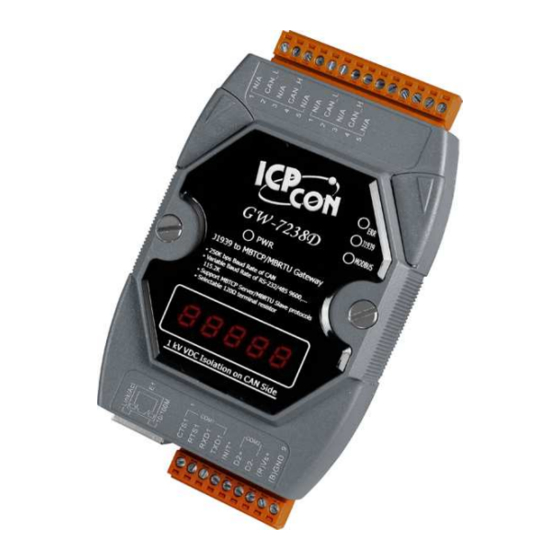
Appearance and pin assignments
Table 1: COM Connector Pin Assignment
Pin No.
1
2
3
4
5
6
7
8
9
Table 2: CAN bus Connector Pin Assignment
Pin No.
1
2
3
4
5
Name
CTS1
RTS1
RXD1
TXD1
INIT*
Initial pin for enable/disable AUTOEXEC.BAT
(Y)D2+
(G)D2-
(R)VS+
(B)GND
Name
N/A
CAN_L
N/A
CAN_H
N/A
Description
CTS pin of COM1 (RS-232)
RTS pin of COM1 (RS-232)
RXD pin of COM1 (RS-232)
TXD pin of COM1 (RS-232)
Data+ pin of COM2 (RS-485)
Data- pin of COM2 (RS-485)
V+ of power supply
GND of power supply
Description
Not Connected
CAN_L bus line (dominant low)
Not Connected
CAN_H bus line (dominant high)
Not Connected
GW-7238D Quick Start v1.0 Nov. 2011
Quick Start
Nov. 2011 Version 1.0
1 1 1 1 / / / / 12 12 12 12
Advertisement

Subscribe to Our Youtube Channel
Related Manuals for ICP DAS USA GW-7238D


Summary of Contents for ICP DAS USA GW-7238D
- Page 1 GW-7238D Quick Start v1.0 Nov. 2011 Quick Start Nov. 2011 Version 1.0 Package checklist The package includes the following items: One GW-7238D hardware module One Quick Start One software utility CD One screw driver One RS-232 cable (CA-0910) Note: If any of these items are missed or damaged, contact the local distributors for more information.
-
Page 2: Led Indication
GW-7238D Quick Start v1.0 Nov. 2011 Figure 1: Appearance of the GW-7238D LED Indication Table 3: LED indication of the GW-7238D LED Name GW-7238D Status LED Status Firmware is running PWR LED Power Failure No Error ERR LED Error Blink... -
Page 3: Installation
5-digits 7-segment LED Displays Figure 2: The meaning of the 7-segment LED Installation If users want to start the GW-7238D normally, it needs to follow these steps to install the GW-7238D below: Step1: Check GW-7238D Firmware Mode Users need to set the dip-switch to the “Normal” position as Figure 3 and reset the power, and then the GW-7238D would run in the operation mode. - Page 4 GW-7238D Quick Start v1.0 Nov. 2011 Step2: J1939 network - CAN bus connection Connect the CAN ports with the GW-7238D modules and ECU (e.g. engine) in J1939 network using the following structure as Figure 4. Figure 4: CAN bus Wire Connection...
- Page 5 GW-7238D Utility Configuration Modbus Network Configuration The GW-7238D and the controller must be set the same serial communication parameters or be on the same subnet via Ethernet communication of the Modbus network configuration.The Modbus network configuration screen from the GW- 7238D is shown as Figure 7.
- Page 6 The device NAME should be set according to the application and the vendor where the module is being used based on the J1939 network specification. The J1939 network configuration screen from the GW-7238D is shown as Figure 8. Figure 8: Modbus configuration screen...
- Page 7 Upload Parameter to the GW-7238D After the previous parameter settings, users need to upload the parameters to the GW-7238D. Please refer to the following figure to finish the operation. 7 7 7 7 / / / / 12 12 12 12...
- Page 8 Read a value of one word in the address 30001. [Request] (Byte0, Byte1... Byten) (Hex) 01 04 00 00 00 01 31 CA(CRC) GW-7238D responds a value of one word in the address 30001. [Response](Byte0, Byte1... Byten) (Hex) 01 04 02 12 34...
- Page 9 GW-7238D Quick Start v1.0 Nov. 2011 Start or Stop sending J1939 output message 1、Using the Modbus command as below: FC6 Write single register (4xxxx) for AO Example: Start sending J1939 output message In the address 42009, write the value in 0x00.
- Page 10 [Request] (Byte0, Byte1... Byten) (Hex) 00 00 00 00 00 06 01 04 00 00 00 01 GW-7238D responds a value of one word in the address 30001. [Response](Byte0, Byte1... Byten) (Hex) 00 00 00 00 00 05 01 04 02...
-
Page 11: Troubleshooting
GW-7238D Quick Start v1.0 Nov. 2011 Troubleshooting Item Trouble state Solution CAN Bus Transmission Fail Make sure the CAN bus wiring is (Power LED Blink per 100 ms) connected, and connected to the correct pin. CAN Bus-Off Make sure the CAN bus wiring... -
Page 12: Technical Support
IP address(192.168.255.1) Technical Support If you have problems about using the GW-7238D, please contact ICP DAS Product Support. Email: Service@icpdas.com 12 12 12 12/ / / / 12 12 12 12...
Need help?
Do you have a question about the GW-7238D and is the answer not in the manual?
Questions and answers