Table of Contents
Advertisement
Available languages
Available languages
Advertisement
Chapters
Table of Contents

Related Manuals for HBM T22


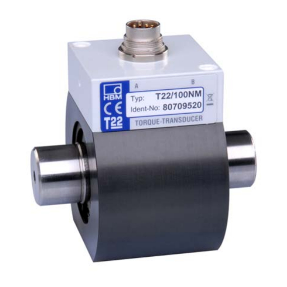
Summary of Contents for HBM T22
- Page 1 Mounting Instructions | Montageanleitung English Deutsch...
- Page 2 Tel. +49 6151 803-0 Fax +49 6151 803-9100 info@hbm.com www.hbm.com Mat.: 7-2001.2302 DVS: A2302-10.0 HBM: public 02.2018 E Hottinger Baldwin Messtechnik GmbH. Subject to modifications. All product descriptions are for general information only. They are not to be understood as a guarantee of quality or durability.
- Page 3 Mounting Instructions | Montageanleitung English Deutsch...
-
Page 4: Table Of Contents
10.1 Accessories for the T22 ........ -
Page 5: Safety Instructions
Safety instructions Safety instructions Designated use The T22 torque transducer is used exclusively for torque measurement tasks, and directly associated control and regulatory tasks. Use for any additional purpose shall be deemed to be not as intended. In the interests of safety, the transducer should only be operated as described in the Operating Manual. - Page 6 Symbols for application and disposal instructions, as well as useful information: Notice Means that important information about the product or its handling is being provided. CE mark The CE mark enables the manufacturer to guarantee that the product complies with the requirements of the relev A2302-10.0 HBM: public...
- Page 7 Safety instructions ant EC directives (the Declaration of Conformity can be found at http://www.hbm.com/HBMdoc). Statutory waste disposal mark In accordance with national and local environmental pro tection and material recovery and recycling regulations, old devices that can no longer be used must be disposed of separately and not with normal household garbage.
- Page 8 The only permitted exceptions to the above requirements are if the various parts and assemblies of the machine are already fully protected by the design of the machine or by existing safety precautions. A2302-10.0 HBM: public...
-
Page 9: Application
Application Application The T22 torque transducer measures static and dynamic torques on rotating or stationary machine parts in any rotation direction. A2302-10.0 HBM: public... -
Page 10: Mounting
The torque transducer can be installed with any orientation (see also Chapter 3.3.1). Installation options CAUTION The permitted load limits set out in the specifications (see Page 20) must be complied with. Side A Side B Measuring side Drive side Fig. 3.1 Installation options with couplings A2302-10.0 HBM: public... -
Page 11: Couplings
3.3.1 Mounting position with couplings The T22 torque transducer can be operated with bellows couplings in any mounting position (horizontally, vertically or at an angle). When operating ver tically or at an angle, please make sure that the additional elements are adequately supported. - Page 12 When mounting the coupling, the permissible longitudinal and lateral forces, and the limit bending moments of the torque transducer must not be exceeded (see Chap. 8)! Hold the coupling on the clamping element when tightening the clamping bolts. A2302-10.0 HBM: public...
-
Page 13: Electrical Connection
If this cannot be avoided (in cable pits, for example), maintain a minimum distance of 50 cm and also draw the measurement cable into a steel tube. Avoid transformers, motors, contactors, thyristor controls and similar stray‐field sources. A2302-10.0 HBM: public... -
Page 14: Connector Plug
Torque measurement signal, voltage output "5 V Ground torque, voltage output Ground supply and current output Supply voltage +11.5 ... 30 V No function No function No function No function gy/pk Torque measurement signal, current output bu/rd 10"8mA Cable shield A2302-10.0 HBM: public... -
Page 15: Cable Extension
Cable extension Extension cables must be shielded and of low capacitance. We recommend the use of HBM cables, which satisfy these requirements. With cable extensions it is important to ensure that a good connection is provided, with minimum contact resistance and good insulation. This is why all the connections should be soldered or at least made with secure, stable terminals or screwed connectors. -
Page 16: Shielding Design
In the case of interference due to potential differences (compensating cur rents), supply voltage zero and housing ground must be disconnected on the amplifier and a potential equalization line established between the transducer housing and the amplifier housing (copper conductor, 10 mm wire cross‐sec tion). A2302-10.0 HBM: public... -
Page 17: Loading Capacity
Loading capacity Loading capacity The torque transducer T22 can be used to measure static and dynamic torques. Nominal torque can be exceeded statically up to the limit torque. If the nominal torque is exceeded, additional irregular loading is not permissible. This includes longitudinal forces, lateral forces and bending moments. -
Page 18: Speed Limits
80 % M Vibration bandwidth Lower torque limit Fig. 5.1 Permissible dynamic loading Speed limits The torque transducer T22 enables measuring range‐dependent torque mea surements of between 9 000 rpm and 16 000 rpm. Limit values, see Chapter 8. A2302-10.0 HBM: public... -
Page 19: Torque Display
If a clockwise torque is applied, a positive output signal is present (0 … +5 V or +10 … +18 mA). Maintenance The torque transducer T22 is practically maintenance‐free. We recommend having the low‐friction special bearing replaced after approx. 20 000 operating hours at the Darmstadt factory. The calibration is also checked at this time. -
Page 20: Dimensions
Dimensions Dimensions Measuring range 0,5 Nm … 2 Nm Ø45±0.1 Ø17.2 Measuring side Dimensions in mm (1 mm = 0.03937 inches) A2302-10.0 HBM: public... - Page 21 (1 mm = 0.03937 inches) Measuring Dimensions in mm (1 mm = 0.03937 inches) range ∅d ∅d (N⋅m) "0.05 "0.1 39 31 15 48 52.75 42 35 18 52 77.5 47.5 50 55 120 26 65 97.5 57.5 75.5 M5 10 A2302-10.0 HBM: public...
-
Page 22: Specifications
(rated) sensitivity) "0.5 Voltage output "0.5 Current output Output signal at torque = zero Voltage output 0"0.2 Current output 10"0.2 Nominal output signal Voltage output at positive nominal (rated) torque at negative nominal (rated) torque A2302-10.0 HBM: public... - Page 23 Residual ripple Voltage output < 100 Current output < 0.1 Effect of temperature per 10 K in the nominal (rated) temperature range on the output sig nal, related to the actual value of the "0.2 signal span A2302-10.0 HBM: public...
- Page 24 DIN 1319, related to the variation of the v"0.1 output signal Maximum level control range Voltage / current v120 output General information Immunity from interference DIN EN 61326-1 und EN 61326-2-3 Cable‐led HF interference 150 kHz-80 MHz A2302-10.0 HBM: public...
- Page 25 EN 60529 Nominal (rated) ° +5...+45 temperature range Operating ° temperature range 0...+60 Storage ° temperature range -5...+70 Environmental influences - Part 2-27: Test procedure - testing: Impact per EN 60068-2-27:20097 Number 1000 Duration Acceleration (half sine) A2302-10.0 HBM: public...
- Page 26 Torsion angle at Deg. 0.20 0.39 0.39 0.26 0.21 0.21 0.15 0.16 0.22 0.10 0.14 Balance quality level per G 6.3 DIN ISO 1940 Max. limits for relative shaft + 4500 μm ‐1 (n in min vibration (peak‐to‐peak) A2302-10.0 HBM: public...
- Page 27 1 % of the nominal (rated) torque. The nominal (rated) torque must not be exceeded. Note the maximum moment (T ) of the couplings. Relative undulations in the shaft stub connection area, based on DIN 45670/VDI 2059. A2302-10.0 HBM: public...
-
Page 28: Accessories
Accessories Accessories 10.1 Accessories for the T22 To be ordered separately. S Transducer connection cable, 5 m long, order no. 3-3301.0158 S Transducer connection cable, 10 m long, order no. 3-3301.0159 S Cable socket, 12‐pin (Binder), order no. 3-3312.0268 S Bellows couplings S Junction box VK20A, order no. -
Page 29: Bellows Couplings
Accessories 10.2 Bellows couplings Dimensions in mm Measuring range 0.5 Nm (1 mm = 0.03937 inches) (42) Fig. 10.1 Bellow coupling, measuring range 0.5 Nm A2302-10.0 HBM: public... - Page 30 Accessories Dimensions in mm Measuring range 1 Nm (1 mm = 0.03937 inches) (42) Fig. 10.2 Bellow coupling, measuring range 1 Nm A2302-10.0 HBM: public...
- Page 31 Accessories Dimensions in mm Measuring range 2 Nm … 1 kNm (1 mm = 0.03937 inches) T22 with mounted couplings Fig. 10.3 Bellow coupling, measuring range 2 Nm … 1 kNm A2302-10.0 HBM: public...
- Page 32 See Fig. 10.2 0002 3-4413. 3…12.7 0003 3-4412. 16.5 15...28 0020 3-4412. 24...35 9.5 172 0021 3-4412. 40...60 M12 39 246 1.5 0022 Connection holes D as requested by the customer within specified limits. Boring tolerance H7. A2302-10.0 HBM: public...
-
Page 33: Specifications Bellows Couplings
0.05 41.9 0.06 0.18 0.08 1000 3500 Measuring Spring stiffness Material Tightening torque for range hub and mounting clamping bolts axial radial (N⋅m) ring (N⋅m) (N/mm) (N/mm) 13.4 27.4 84.3 20.6 55.8 3710 Aluminum 11000 9010 Steel A2302-10.0 HBM: public... - Page 34 Accessories A2302-10.0 HBM: public...
- Page 35 Mounting Instructions | Montageanleitung English Deutsch...
- Page 36 10.1 Zubehör für T22 ......... . .
-
Page 37: Sicherheitshinweise
Sicherheitshinweise Sicherheitshinweise Bestimmungsgemäßer Gebrauch Die Drehmoment‐Messwelle T22 ist ausschließlich für Drehmoment‐Messauf gaben und direkt damit verbundene Steuerungs‐ und Regelungsaufgaben zu verwenden. Jeder darüber hinausgehende Gebrauch gilt als nicht bestim mungsgemäß. Zur Gewährleistung eines sicheren Betriebes darf der Aufnehmer nur nach den Angaben in der Bedienungsanleitung verwendet werden. - Page 38 - Sachschaden, leichte oder mittlere Kör perverletzung zur Folge haben könnte. Symbole für Anwendungs‐ und Entsorgungshinweise sowie nützliche Informa tionen: Hinweis Weist darauf hin, dass wichtige Informationen über das Produkt oder über die Handhabung des Produktes gegeben werden. A2302-10.0 HBM: public...
- Page 39 Mit der CE‐Kennzeichnung garantiert der Hersteller, dass sein Produkt den Anforderungen der relevanten EG‐ Richtlinien entspricht (die Konformitätserklärung finden Sie unter http://www.hbm.com/HBMdoc). Gesetzlich vorgeschriebene Kennzeichnung zur Entsorgung Nicht mehr gebrauchsfähige Altgeräte sind gemäß den nationalen und örtlichen Vorschriften für Umweltschutz und Rohstoffrückgewinnung getrennt von regulärem...
- Page 40 Teile der Drehmoment‐Messwelle außerhalb des Verkehrs‐ und Arbeitsbereiches von Personen installiert sind. Von den vorstehenden Forderungen darf nur abgewichen werden, wenn die Maschinenteile und ‐stellen schon durch den Bau der Maschine oder bereits vorhandene Schutzvorkehrungen ausreichend gesichert sind. A2302-10.0 HBM: public...
-
Page 41: Anwendung
Anwendung Anwendung Die Drehmoment‐Messwelle T22 misst statische und dynamische Drehmo mente an drehenden oder ruhenden Maschinenteilen bei beliebiger Drehrich tung. A2302-10.0 HBM: public... -
Page 42: Montage
Die Einbaulage der Drehmoment‐Messwelle ist beliebig (siehe auch Kap 3.3.1). Montagemöglichkeiten VORSICHT Die in den technischen Daten (siehe Seite 20) angegebenen zulässigen Belas tungsgrenzen sind unbedingt einzuhalten. Seite A Seite B Messseite Antriebsseite Abb. 3.1 Montagemöglichkeiten mit Kupplungen A2302-10.0 HBM: public... -
Page 43: Kupplungen
H7/j6 ergibt. 3.3.1 Einbaulage mit Kupplungen Die Drehmoment‐Messwelle T22 kann mit den Faltenbalg‐Kupplungen in belie biger Einbaulage (horizontal, vertikal oder schräg) betrieben werden. Achten Sie bitte beim vertikalen und schrägen Betrieb darauf, dass zusätzliche Mas sen ausreichend abgestützt sind. - Page 44 Montage VORSICHT Bei der Kupplungsmontage dürfen die zulässigen Längs‐ und Querkräfte sowie Grenzbiegemomente der Drehmoment‐Messwelle (siehe Kapitel 8), nicht über schritten werden! Beim Anziehen der Spannschrauben die Kupplung am Klemmelement festhal ten. A2302-10.0 HBM: public...
-
Page 45: Elektrischer Anschluss
Allgemeine Hinweise Für die elektrische Verbindung zwischen Drehmomentaufnehmer und Mess verstärker empfehlen wir die geschirmten und kapazitätsarmen Messkabel von HBM zu verwenden. Achten Sie bei Kabelverlängerungen auf eine einwandfreie Verbindung mit ge ringstem Übergangswiderstand und guter Isolation. Alle Steckverbindungen oder Überwurfmuttern müssen fest angezogen werden. -
Page 46: Anschlussstecker
Nicht belegt Messsignal Drehmoment, Spannungs ausgang "5 V Masse Drehmoment, Spannungsaus gang Masse Versorgung und Stromausgang Versorgungsspannung +11,5 ... 30 V Nicht belegt Nicht belegt Nicht belegt Nicht belegt gr/rs Messsignal Drehmoment, Stromaus bl/rt gang 10"8 mA Kabelschirm A2302-10.0 HBM: public... -
Page 47: Kabelverlängerung
Anschlussschema T22 Kabelverlängerung Verlängerungskabel müssen abgeschirmt und kapazitätsarm sein. Wir empfeh len die Verwendung von HBM‐Kabeln, die diese Voraussetzungen erfüllen. Bei Kabelverlängerungen ist auf einwandfreie Verbindung mit geringstem Über gangswiderstand und gute Isolation zu achten. Deshalb sollen alle Verbindun gen gelötet, zumindest aber mit sicheren, stabilen Klemmen oder verschraub... -
Page 48: Schirmungskonzept
Messsignal nicht. Bitte beachten Sie die Anschlusshinweise. Bei Störungen durch Potentialunterschiede (Ausgleichsströme) trennen Sie am Messverstärker die Verbindungen zwischen Betriebsspannungsnull und Ge häusemasse und legen Sie eine Potentialausgleichsleitung zwischen Aufneh mergehäuse und Messverstärkergehäuse (Kupferleitung, 10 mm Leitungs querschnitt). A2302-10.0 HBM: public... -
Page 49: Belastbarkeit
Belastbarkeit Belastbarkeit Die Drehmoment‐Messwelle T22 eignet sich zum Messen statischer und dyna mischer Drehmomente. Das Nenndrehmoment darf statisch bis zum Grenzdrehmoment überschritten werden. Wird das Nenndrehmoment überschritten, sind weitere irreguläre Be lastungen nicht zulässig. Hierzu zählen Längskräfte, Querkräfte und Biegemo... -
Page 50: Drehmomentanzeige
80 % M Schwingbreite Untere Drehmomentgrenze Abb. 5.1 Zulässige dynamische Belastung Drehzahlgrenzen Die Drehmoment‐Messwelle T22 erlaubt messbereichsabhängig Drehmoment messungen von 9 000 min bis 16 000 min . Grenzwerte siehe Kapitel 8.. Drehmomentanzeige Drehmoment Wird ein rechtsdrehendes Moment (im Uhrzeigersinn) eingeleitet, steht ein po... -
Page 51: Wartung
Wartung Wartung Die Drehmoment‐Messwelle T22 ist weitgehend wartungsfrei. Wir empfehlen, die reibungsarmen Speziallager nach ca. 20 000 Betriebsstunden im Werk Darmstadt wechseln zu lassen. Bei dieser Gelegenheit wird auch die Kalibrie rung überprüft. A2302-10.0 HBM: public... -
Page 52: Abmessungen
Abmessungen Abmessungen Messbereiche 0,5 Nm bis 2 Nm Ø45±0,1 Ø17,2 Messseite Abmessungen in mm A2302-10.0 HBM: public... - Page 53 ∅17.2 ∅d Messseite Abmessungen in mm Abmessungen in mm Mess bereich ∅d ∅d (N⋅m) "0,05 "0,1 39 31 15 48 52,75 42 35 18 52 77,5 47,5 50 55 120 26 65 97,5 57,5 75,5 M5 10 A2302-10.0 HBM: public...
-
Page 54: Technische Daten
(Abweichung der tatsächlichen Aus gangsgröße bei vom Nenn kennwert) "0,5 Spannungsausgang "0,5 Stromausgang Ausgangssignal bei Drehmoment = Null Spannungsausgang 0"0,2 Stromausgang 10"0,2 Nennausgangssi gnal Spannungsausgang bei positivem Nenndrehmo ment bei negativem Nenndrehmo ment Stromausgang bei positivem Nenndrehmo ment A2302-10.0 HBM: public... - Page 55 Temperatureinfluss pro 10 K im Nenntemperaturbereich auf das Ausgangssignal, be zogen auf den Ist wert der Signal "0,2 spanne auf das Nullsignal, bezogen auf den "0,5 Nennkennwert Energieversorgung Bereich der Nenn versorgungsspan nung 11,5 ... 30 (DC) Stromaufnahme im < 0,2 Messbetrieb A2302-10.0 HBM: public...
- Page 56 Maximaler Aus steuerbereich Spannungs‐/ v120 Stromausgang Allgemeine Angaben Störfestigkeit DIN EN 61326-1 und EN 61326-2-3 Leitungsgeführte HF‐Störungen 150 kHz-80 MHz ESD (Entladung stat. Elektrizität) Kontaktenladung Luftentladung Elektromagnet. Feld 80 MHz…2000 MHz 2000 MHz… 2700 MHz Burst (schnelle Transienten) A2302-10.0 HBM: public...
- Page 57 EN 60068-2-27:2009 Anzahl 1000 Dauer Beschleunigung (Halbsinus) Umgebungseinflüsse - Teil 2-6: Prüfverfahren - Prüfung: Schwingen (sinusförmig) nach EN 60068-2-6:2008 Frequenzbereich 5 ... 65 Dauer Beschleunigung (Amplitude) Nenndrehzahl ‐1 20.000 16.000 12.000 9.000 Belastungsgrenzen Grenzdrehmo ment, bezogen auf A2302-10.0 HBM: public...
- Page 58 G 6,3 DIN ISO 1940 Zul. max. Schwing + 4500 μm weg des Rotors ‐1 (n in min (Spitze/Spitze) Effekt. Schwing geschwindigkeit ‐1 (n in min im Bereich des mm/s Gehäuses entspre chend VDI 2056 A2302-10.0 HBM: public...
- Page 59 Im Messergebnis können sich die zul. Biegemomente, Längs‐ und Querkräfte wie ca. 1 % des Nenndrehmomentes auswirken. Das Nenndrehmoment darf nicht überschritten werden. Bitte beachten Sie das maximale Moment (T ) der Kupplungen. Rel. Wellenschwingungen im Bereich der Anschluss‐Wellenstümpfe in Anlehnung an DIN 45670/VDI 2059. A2302-10.0 HBM: public...
-
Page 60: Zubehör
Zubehör Zubehör 10.1 Zubehör für T22 Zusätzlich zu beziehen. S Aufnehmer‐Anschlusskabel, 5 m lang, Bestell‐Nr. 3‐3301.0158 S Aufnehmer‐Anschlusskabel, 10 m lang, Bestell‐Nr. 3‐3301.0159 S Kabeldose, 12polig (Binder), Bestell‐Nr. 3‐3312.0268 S Faltenbalg‐Kupplungen S Klemmenkasten VK20A, Bestell‐Nr. 1‐VK20A Zubehör für den Klemmenkasten VK20A, Zusätzlich zu beziehen. -
Page 61: Faltenbalg-Kupplungen
Zubehör 10.2 Faltenbalg‐Kupplungen Abmessungen in mm Messbereich 0,5 Nm (42) Abb. 10.1 Faltenbalg-Kupplung, Messbereich 0,5 Nm A2302-10.0 HBM: public... - Page 62 Zubehör Abmessungen in mm Messbereich 1 Nm (42) Abb. 10.2 Faltenbalg-Kupplung, Messbereich 1 Nm A2302-10.0 HBM: public...
- Page 63 Zubehör Abmessungen in mm Messbereich 2 Nm bis 1 kNm T22 mit montierten Kupplungen Abb. 10.3 Faltenbalg-Kupplung, Messbereich 2 Nm … 1 kNm A2302-10.0 HBM: public...
- Page 64 Siehe Abb. 10.1 0001 3-4412. Siehe Abb. 10.2 0002 3-4413. 3…12,7 0003 3-4412. 16,5 15...28 0020 3-4412. 24...35 0021 3-4412. 89 110 40...60 M12 39 246 1,5 0022 Anschlussbohrungen D nach Kundenwunsch innerhalb der angegebenen Grenzen. Bohrungstoleranz H7. A2302-10.0 HBM: public...
-
Page 65: Technische Daten Faltenbalg-Kupplungen
0,00012 0,21 0,00018 0,38 0,0027 0,05 41,9 0,06 0,18 0,08 1.000 3.500 Mess Federsteife Werkstoff Anzugsmoment bereich Nabe und Spannschrauben Befestigungsring (N⋅m) axial (N/mm) radial (N/mm) (N⋅m) 13,4 27,4 84,3 20,6 55,8 3710 Aluminium 11000 9010 Stahl A2302-10.0 HBM: public... - Page 66 Zubehör A2302-10.0 HBM: public...
- Page 67 Zubehör A2302-10.0 HBM: public...
- Page 68 HBM Test and Measurement Tel. +49 6151 803-0 Fax +49 6151 803-9100 info@hbm.com measure and predict with confidence...
Need help?
Do you have a question about the T22 and is the answer not in the manual?
Questions and answers