Table of Contents
Advertisement
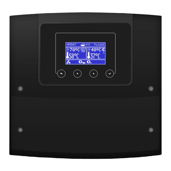
CONTROLLER
ecoMAX360P1-C
FOR PELLET FUEL BOILERS
eSTER_x40*
eSTER_x80*
ecoNET300*
ecoNET.apk
ecoNET.app
www.econet24.com
INSTALLATION AND OPERATING MANUAL
ISSUE: 1.1_EN
* devices are not the standard equipment of the controller.
functions
available
in
additional module B
11-2020
ecoSTER TOUCH*
ecoSTER200*
the
Advertisement
Table of Contents


Need help?
Do you have a question about the eSTER_x40 Series and is the answer not in the manual?
Questions and answers