Table of Contents
Advertisement
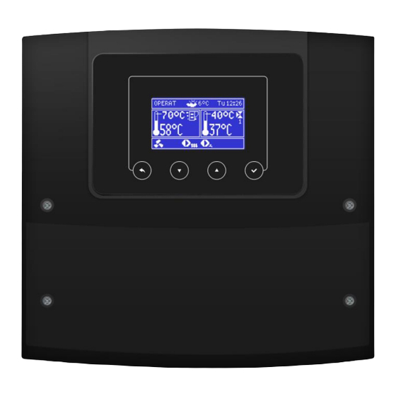
CONTROLLER
ecoMAX360P1-C
FOR PELLET FUEL BOILERS
eSTER_x40*
eSTER_x80*
ecoNET300*
ecoNET.apk
ecoNET.app
www.econet24.com
INSTALLATION AND OPERATING MANUAL
ISSUE: 1.1_EN
* devices are not the standard equipment of the controller.
functions
available
in
additional module B
11-2020
ecoSTER TOUCH*
ecoSTER200*
the
Advertisement
Table of Contents

Related Manuals for KIPI eSTER_x80 Series


Summarization of Contents
Safety Guidelines
Electrical Safety and Disconnection
Ensure power is disconnected and terminals are voltage-free before assembly or repairs.
Operational and Installation Safety
Avoid misuse, apply safety automatics, use qualified personnel for installation, and keep out of reach of children.
General Information
Controller Overview and Function
The ecoMAX360P1-C controls a boiler with automatic solid fuel feeding and igniter.
Documentation and Symbols Guide
Information about the manual, its structure, and the meaning of applied symbols used throughout the document.
User Menu Structure
Main Menu Navigation
Outlines the main menu categories: Information, Boiler settings, HUW settings, Mixer settings, General settings, etc.
Boiler Settings Configuration
Boiler Settings Parameters
Covers preset temperature, weather control, output modulation, feeder settings, and regulation modes.
Controller Interface and Display
Control Panel and Button Functions
Describes the buttons on the control panel and their functions for navigation and parameter editing.
Main Screen Element Overview
Details the elements displayed on the main screen, including modes, temperatures, and status indicators.
Boiler Start-up and Operation Modes
Controller Start-up and Stand-by
Explains how the controller starts, the stand-by mode, and how to manually start the boiler.
Firing Up and Operation Modes
Details the FIRING UP mode for automatic ignition and the OPERATION mode with fan and feeder cycles.
Boiler Regulation Modes
Standard and Fuzzy Logic Modes
Explains the two adjustment modes for stabilizing boiler temperature and their characteristics.
Supervision Mode Operation
Describes the SUPERVISION mode, its applicability, and how the controller enters it.
Burner Operation Modes
Burning Off and Stop Modes
Details the BURNING OFF mode for cleaning and the STOP mode for awaiting operation signals.
Grate Operation and Burner Cleaning
Explains the grate mode for alternative fuels and the burner cleaning function.
HUW Settings and Mixer Control
HUW Tank Temperature Management
Covers preset HUW temperature, hysteresis, SUMMER function, and container disinfection.
Mixer Circle Configuration
Details settings for mixer circles, including weather sensors and room thermostats.
Mixer Settings and Weather Control
Mixer Settings with Room Thermostat
Explains how to connect and configure room thermostats for mixer temperature control.
Weather Control Configuration
Details how to activate and adjust weather control for boiler and mixer temperatures.
Heating Curve and Night Settings
Heating Curve Adjustment Tips
Provides tips on choosing proper heating curves based on building insulation and temperature feedback.
Night Decrease Settings
Explains how to set time intervals for reducing preset temperatures for energy saving.
Schedule and Pump Control
Working According to Schedule
Describes how to set time intervals for switching the boiler on and off.
Circulation Pump Control
Details the functionality and connection of the circulation pump via an additional module.
Fuel Level and Manual Control
Fuel Level Configuration and Monitoring
Explains how to configure, activate, and monitor the fuel level indicator.
Manual Device Control
Allows manual activation of devices like pumps and feeders for checking operation and connections.
Installation and Service Settings
Installation Overview and Requirements
Introduces the section on installation and service settings for the controller.
Hydraulic Schemes
Scheme with Three-Way Actuator
Illustrates a hydraulic scheme with a three-way thermostatic actuator for return water temperature protection.
Heating Circuits and HUW Container
Two Adjustable Heating Circuits
Shows a scheme with two adjustable heating circuits and the HUW container, detailing recommended settings.
Heat Buffer System
Scheme with Heat Buffer
Details a scheme with a heat buffer, including recommended settings for various components.
Technical Data and Installation Conditions
Technical Specifications
Lists electrical, environmental, and physical specifications of the controller.
Environmental and Installation Requirements
Outlines environmental conditions, installation requirements, and prohibitions for controller installation.
Electrical System Connection
Connecting the 230 VAC Mains
Details the safe connection of the 230 VAC mains voltage, including safety precautions.
Wiring and Cable Management
Explains proper wiring, securing cables, and ensuring protection against heat and damage.
Controller Terminal Box Details
Terminal Connections and Cable Management
Shows terminal box layout for 230V and <15V, cable connection rules, and STB capillary handling.
Electric Scheme and Connections
Electrical Connection Diagram
Provides a detailed scheme of electrical connections for various components and sensors.
Additional Module B Connections
Scheme of Additional Module B
Details electrical connections for the additional B module, including sensors, pumps, and servomotors.
Temperature Sensors
Connecting and Checking Temperature Sensors
Explains how to connect CT4/CT6-P sensors and how to check their resistance for proper function.
Connecting Weather Sensor
Guides on installing and configuring the weather sensor (CT4-P/CT6-P) for temperature control.
Sensor Checking and Optical Sensor
Temperature Sensor Resistance Values
Provides tables of resistance values for CT4, CT4-P, and CT6-P sensors at different temperatures.
Optical Sensor Connection
Details the connection of the optical sensor for flame detection and its menu information.
Reserve Boiler and Alarm Signaling
Connecting a Reserve Boiler
Explains how to connect and control a reserve boiler (gas/oil) via the additional B module.
Alarm Signaling Connection
Details connecting external devices for alarm signaling via a relay to the additional B module.
Mixer Connection and Circulation Pump
Mixer Servomotor Connection
Guides on connecting mixer servomotors, checking their operation, and setting parameters.
Circulation Pump Connection
Notes that circulation pump connection is only possible after purchasing an additional module B.
Safety Temperature Limiter and Room Thermostats
Safety Temperature Limiter (STB)
Explains the STB controller version, its built-in limiter, and how to reset it.
Room Thermostat Connections
Details connecting universal and wireless room thermostats/panels to the controller.
Wired Room Panel and Internet Module
Wired Room Panel Connection
Describes the four-wire connection for ecoSTER200/TOUCH room panels.
Internet Module Connection
Guides on connecting the ecoNET300 Web module via ecoLINK2 interface and configuring WiFi.
Service Menu Structure
Service Settings Categories
Lists the main categories within the service menu, requiring a password for access.
Burner Service Parameters
Burner Firing-up Parameters
Explains parameters related to burner ignition, fuel dose, flame detection, and airflow during firing up.
Burner Operation and Burning Off
Details parameters for burner operation modes, fuel calorific, capacity, and the burning off process.
Boiler and CH/HUW Service Parameters
Boiler Thermostat and Cooling Parameters
Covers thermostat selection, minimum/maximum temperatures, and boiler cooling temperature settings.
CH Activation and HUW Temperature Settings
Explains parameters for CH pump activation, HUW tank temperature, and potential overheating risks.
Buffer and Mixer Service Parameters
Buffer Support and Loading Parameters
Details parameters for buffer support, loading start, and loading end temperatures.
Mixer Support and Temperature Settings
Covers mixer support options, thermostat selection, and mixer temperature limits.
Mixer and Other Service Parameters
Mixer Control Parameters
Explains parameters like proportional range, integration time, valve opening, and mixer input dead zone.
Other Service Parameters
Covers parameters for advanced setup, service counters, restoring settings, and output H configuration.
Alarms Descriptions
Boiler and Burner Overheating Alarms
Details alarms for boiler/burner max temperature exceeding and STB open contact.
Sensor Damage and Firing Up Alarms
Explains alarms for boiler/feeder sensor damage and failed firing up attempts.
Additional Functions and Component Replacement
Protective Functions
Describes functions like power stoppage, antifreezing, preventive cooling, and pump anti-standstill.
Fuse and Software Replacement
Guides on replacing the fuse and updating the controller's software.
Possible Faults Description
Device Operation and Temperature Faults
Lists symptoms and checks for faults related to device operation, display differences, and temperature measurement.
Pump and Feeder Faults
Details troubleshooting steps for CH pump, fan, fuel feeder not working, and HUW pump issues.
Need help?
Do you have a question about the eSTER_x80 Series and is the answer not in the manual?
Questions and answers