Table of Contents

Subscribe to Our Youtube Channel
Related Manuals for KIPI ecoMAX920 P1-CH


Summary of Contents for KIPI ecoMAX920 P1-CH
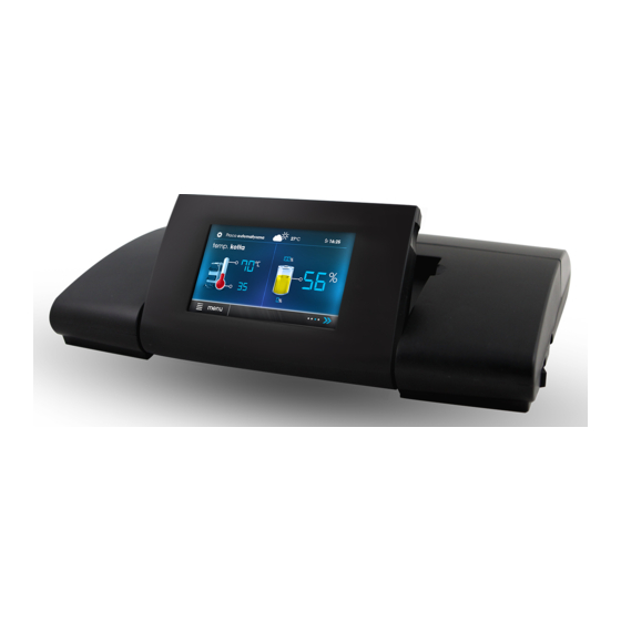
- Page 1 CONTROLER ecoMAX920P1-CH FOR BLOWING TYPE BOILER FOR SOLID FUEL ecoNET300* ecoNET.apk ecoNET.app www.econet24.com * the device is not a standard equipment of the regulator. I OPERATING AND INSTALLATION MANUAL ISSUE: 1.0 09-2020...
- Page 2 LIVE ELECTRICAL DEVICE! Before performing any activities related to power supply (connecting cables, device installation, etc.), make sure that the regulator is not connected to the mains. Installation should be performed by a person with appropriate electrical qualifications. Incorrect connection of the wires may damage the regulator.
-
Page 3: Table Of Contents
TABLE OF CONTENTS 12.10 CONNECTION EXHAUST TEMPERATURE 23 12.11 TEMPERATURE SENSORS CHECKING 1 INFORMATION REGARDING SAFETY 12.12 CONNECTING THE OPTICAL SENSOR 2 GENERAL INFORMATION 12.13 CONNECTION OF BACK-UP BOILER 3 INFORMATION ABOUT DOCUMENTATION 12.14 CONNECTION OF ALARM SIGNALING 4 DOCUMENTATION STORAGE 5 GRAPHIC SYMBOLS USED 12.15 CONNECTING THROTTLE ACTUATOR 6 WEEE DIRECTIVE 2012/19 / EU 6... - Page 4 • The structure of the regulator may not be Safty advices modified under any circumstances. • The controller uses electronic disconnection Safety requirements are specified in of connected devices (operation type individual sections of this manual. Apart from 2Y in accordance with PN-EN 60730-1) them, in particular, the following and micro-disconnection (operation requirements must be observed.
-
Page 5: General Information
- the symbol indicates useful information 2 General Information and tips. The ecoMAX920P1-CH regulator is designed symbol indicates important to control the operation of a furnace and a information which affect property hot air heater with a heat exchanger. The damage, health or life for humans and furnace is adapted to burn pellet type fuel, domestic animals. - Page 6 Manual ecoMAX920P1-CH...
- Page 7 Cleaning Main menu - structure Burner cleaning Cleaning intensity Main menu Exchanger cleaning time Information Exchanger cleaning break Device settings Schedule Furnance settings Built-in thermostat Themrmostat bulit-in Work on the schedule Thermostat mode off / schedule - Comfort General settings...
-
Page 8: Firing Up Mode
Controler peration possible change information presented. Decription of main screen Turning the stove on and off The stove is started by pressing any place the screen with the inscription "Stove off", then the following message will appear: Turn on the regulator? There is a second method to turn on the stove. -
Page 9: Regulation Modes
Mode OPERATION The parameters of the burner power levels are available in the menu: In the OPERATION mode, the burner fan Furnance settings → Power modulation operates continuously, the fuel feeder is The controller decides about the power of the activated cyclically, where the cycle consists burner with which the furnace will work at of the feeder operation time and the fuel... -
Page 10: Manual Mode
MANUAL mode temperature in this mode gradually In the MANUAL mode, the burner operates at drops. Incorrect settings can lead minimum power for the time set in the to overheating. service parameter Working time with The maximum burner operation time in the minimum power, exhaust... -
Page 11: Description Of Night Decrease
rotary burner cleaning mechanism will be temperature. activated and then the burner will fire up again. The furnace is cleaned in the FIRING UP and BURNING OFF mode. Additional parameters responsible for cleaning are grouped in the menu: Service settings → Burner settings → Cleaning Exchanger cleaning service The regulator enables cleaning the exchanger... -
Page 12: Fuel Level Configuration
Active night-time decreases are signaled on • Support for the fuel level indicator Each time after filling the fuel tank, press the screen by the symbol and hold the current value of the fuel level, The Reduction value parameter is used to set then the prompt "Set the fuel level to 100%"... -
Page 13: Room Panel
Settings of operating modes of the built-in damper is closed only after the burner is thermostat, which is responsible for heating extinguished and the exhaust fan is stopped. in zone I. Thermostat support should be Feeder Test enabled by setting the Thermostat selection parameter to Built-in in the menu: Device The controller allows you to test the burner settings. - Page 14 ecoNET.app...
- Page 16 INSTALLATION MANUAL AND SERVICE SETTINGS ecoMAX920P1-CH...
- Page 17 Hydraulic diagram Hydraulic diagram of the heating system for hot air supply: 1 - furance, 2 - controller, 3 - exhaust gas temperature sensor, 4 - exchanger temperature sensor, 5 - supply temperature sensor, 6 - exhaust fan, 7 - burner fan and burner feeder, 8 - air damper actuator, 9 - room panel with a room thermostat function, 10 - external air intake, 11 - air supply duct, 12 - internal temperature sensor, 13 - intake filter, 14 - chimney installation, 15 - external temperature sensor, I ...
-
Page 18: With
exposed to vibrations greater than those Technical data corresponding to typical conditions of wheel Regulator power supply 230 V~, 50 Hz transport. Current consumed by the 0,04 A regulator Maximum rated current 6 (6) A IP protection class The degree of protection of IP20 the regulator The casing of the regulator provides IP20... - Page 19 while the terminals of the protective strip equipped with a set of plugs inserted must be tightened, even if there is no wire into the connectors for supplying ~ connected to the 230V devices. With a metal zero strip marked with the terminal.
- Page 20 Connecting the cables to the controller: 1 - cable openings, 2 - placing clamps (they must be broken off), 3 - incorrectly connected cable (it is forbidden to wind excess cables inside the device and leave wires without wires), 4 - correctly connected cable, 5 - cable clamp , 6 - connector.
-
Page 21: Electrical Scheme
Electrical diagram... -
Page 22: Connecting Weather Sensor
regulator terminals. The sensor should be Connecting temperature sensors screwed to the wall with mounting screws. The regulator cooperates with sensors of the Access to the holes for mounting screws is CT4 type. The use of other types of sensors obtained after unscrewing the cover of the is prohibited. -
Page 23: Connecting The Optical Sensor
exceed ° 1029 1040 1051 1108 1122 1136 1192 1209 1225 1278 1299 1319 1369 1392 1416 1462 1490 1518 1559 1591 1623 1659 1696 1733 CT6-P (weather) External Min. Nom. Max. Temp. °C Ω Ω Ω 901,6 901,9 902,2 921,3 921,6 921,9... -
Page 24: Connection Of Alarm Signaling
terminals 43-44 regulator. An exemplary diagram of a system for connecting a reserve boiler to the regulator: 1 - regulator, 2 - reserve boiler (gas or oil), 3 - relay RM 84-2012-35-1012 and GZT80 RELPOL base. As standard, the controller is not equipped with a relay. -
Page 25: Connecting Room Panel
safety temperature limiter must have rated operating voltage of at least ~ 230 V and should have applicable approvals. Dangerous voltage is present on terminals 1-2. If the STB is not installed on terminals 1-2 of the regulator, a bridge must be used, which should be made with an insulated wire with a cross-section of at least 0.75 mm2, with insulation thick enough to meet the safety... -
Page 26: Service Menu - Structure
Service menu - structure Fan power Entering the menu requires entering Minimum blowing power the service password. Fuel shortage detection time Maximum burner temperature Service Settings Burner stettings Device settings Device Settings Output H Excchanger sensor Display advanced Shutdown hysteresis Restore defaults settings Heater fan start temp Save Defaults Settings... -
Page 27: Description
Description of service parameters Burner Parametr Description Setting a fire Ignition test time Time to check if the furnace is already fired. Only the fan is running. If the flame is bright enough, it enters the OPERATION mode, skipping the FIRING UP mode. - Page 28 Blow-off power Blow-in fan power during blowing while burning off. Purge time Duration of air blow when burning fuel in burning off. Purge break Pause between blowing when burning off fuel in burning off. Purge start The brightness of the flame at which airflow starts, with fuel burnout ...
- Page 29 be reported. Parameter A, B, C FL Parameter related to automatic modulation of the burner power with stabilization of the set burner temperature. Increasing the value increases the speed of the burner power increase. Too high a value may cause instability in maintaining the preset burner temperature. Other parametrs Parametr Description...
-
Page 30: Parameters
Checking the temperature sensor is 7 Description of alarms described in point 12.11 6.4 Unsuccessful firing up attempt alarm will occur after third The maximum temperature of the fuser unsuccessful attempt to automatically fire up has been exceeded the furnace. This alarm may be caused by a If the furnace temperature exceeds 95ºC, faulty igniter or a lack of fuel. -
Page 31: Damage To The Fan Or Rotation
Damage to the fan or the rotation It is not recommended to replace the control sensor panel itself because the program in the panel must be compatible with the program in the The alarm occurs when the fan speed sensor rest of the regulator. -
Page 32: Software Update
fuel Check that the feeder wires are properly connected feeder does terminals. work If the STB temperature limiter is does not feed. connected terminals 1-2, check that the circuit has not been cut off due to overheating of the furnace. Check if the feeder motor is not damaged. - Page 34 Obornicka 71 62-002 Suchy Las Polska Tel. 61 811 70 37 biuro@kipi.pl www.kipi.pl BDO: 000179569...
Need help?
Do you have a question about the ecoMAX920 P1-CH and is the answer not in the manual?
Questions and answers