Table of Contents
Advertisement
Quick Links
GE Consumer & Industrial
Multilin
GE Multilin
215 Anderson Avenue, Markham, Ontario
Canada L6E 1B3
Tel: (905) 294-6222 Fax: (905) 201-2098
Internet: http://www.GEmultilin.com
*1665-0003-CJ*
RELAY TEST TOOL
Instruction Manual
Manual P/N:1601-9021-A1
Manual Order Code: GEK-113388
Copyright © 2007 GE Multilin
ISO9001:2000
GE Multilin's Quality Management
System is registered to ISO9001:2000
QMI # 005094
Advertisement
Table of Contents

Subscribe to Our Youtube Channel
Related Manuals for GE RTT


Summary of Contents for GE RTT
- Page 1 GE Consumer & Industrial Multilin RELAY TEST TOOL Instruction Manual Manual P/N:1601-9021-A1 Manual Order Code: GEK-113388 Copyright © 2007 GE Multilin GE Multilin 215 Anderson Avenue, Markham, Ontario ISO9001:2000 Canada L6E 1B3 Tel: (905) 294-6222 Fax: (905) 201-2098 Internet: http://www.GEmultilin.com...
- Page 2 The contents of this manual are the property of GE Multilin Inc. This documentation is furnished on license and may not be reproduced in whole or in part without the permission of GE Multilin. The content of this manual is for informational use only and is subject to change without notice.
-
Page 3: Table Of Contents
TABLE OF CONTENTS Table of Contents 1: GETTING STARTED ORDERING ............................1 RTT ......................1 RDERING THE ABOUT YOUR NEW RTT UNIT ...................... 2 ....................2 AUTIONS AND ARNINGS ................2 HECK THE ONTENTS OF THE ......................2 SING THIS ANUAL RTT ........................ - Page 4 TABLE OF CONTENTS 4: MOTOR MANAGEMENT THE 369 MOTOR MANAGEMENT RELAY ................. 61 & METERING ..........................61 VERVIEW 369 M ..........62 OTOR ANAGEMENT ELAY ERMINAL AYOUT 369 R ................63 ELAY IRING IAGRAM 369 S ..64 NTERFACING TO THE THROUGH THE NVER ISTA...
-
Page 5: 1: Getting Started Ordering
Multilin RTT Desktop Test Set Chapter 1: Getting Started Getting Started Ordering 1.1.1 Ordering the RTT Select the basic model and the desired features from the selection guide below: Table 1–1: Ordering Codes RTT-Cable RTT DESKTOP TEST SET– INSTRUCTION MANUAL... -
Page 6: About Your New Rtt Unit
NOTE CAUTION Before attempting to install or use the RTT unit, it is important that all DANGER and CAUTION indicators in this manual are reviewed in order to prevent personal injury, equipment damage and/or downtime. The above icons are used to indicate dangers, cautions and notes. -
Page 7: About The Rtt
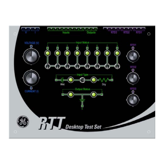
2 contact outputs both monitored via LEDs. The RTT also has 3 channels of RTD resistance simulators. The features of the RTT allow you to test several functions of the relay, such as overcurrent, overvoltage, directional units using the single phase source in a very easy and convenient way. - Page 8 FIGURE 1–1: RTT Details * In order to prevent accidental movement of the Wet/Dry toggle switch, the switch comes with a locking feature: you must pull it upward in order to toggle the RTT between "Wet" and "Dry" input. RTT DESKTOP TEST SET– INSTRUCTION MANUAL...
- Page 9 CHAPTER 1: GETTING STARTED ABOUT YOUR NEW RTT UNIT The figure below shows the cable provided with the RTT. This cable is used to connect to all relays, although for some, it may have to be slightly modified. See the appropriate chapter for details.
- Page 10 ABOUT YOUR NEW RTT UNIT CHAPTER 1: GETTING STARTED The figure below shows the wire labels (see figure 1-2, above), that correspond to the RTT terminals.. RTD1 + RTD1 - RTD1 C RTD2 + RTD2 - 18 AWG RTD2 C...
-
Page 11: Rtt Unit Specifications
DC Voltage:............23.4 VDC @ 200mA Tolerance: ............±5% 1. Fuse Replacement: - Disconnect Power Supply and remove fuse from its holder. - Replace with a 80 mA, 250 V, time-lag fuse. Use ONLY fuses indicated in above specifications. RTT DESKTOP TEST SET– INSTRUCTION MANUAL... - Page 12 Size: 7.5" L × 5.75" W × 3.25" D / 187 mm L × 145 mm W × 81 mm D Weight: 4.95 lb / 2.26 Kg INTERNATIONAL STANDARDS COMPLIANT When used with advanced protection relays such as the GE Multilin Universal Relay family, the RTT complies with most international standards requirements for test and measuring equipment:...
- Page 13 +85°C, 16 hours Sinusoidal Vibration IEC 60255-21:1996, 1988; 10 Hz - 150 Hz, 1G, IEEE C37.1 Z-axis SAFETY TESTS Dielectric Strength Per EN/IEC 61010-1 Up to 1700 VAC, 1 min ISM-Safety EN/IEC 61010-1 ISM-Safety UL/ULC 61010-1 RTT DESKTOP TEST SET– INSTRUCTION MANUAL...
- Page 14 ABOUT YOUR NEW RTT UNIT CHAPTER 1: GETTING STARTED RTT DESKTOP TEST SET– INSTRUCTION MANUAL...
-
Page 15: 2: Using The Rtt On Sr The 469 Motor Management Relay
120 Nickel. All features of RTT can be applied to the SR469 Relay. Although there are no unused terminals on the RTT product cable, a modification to the cable is required in order to fit it to the SR469 terminals. -
Page 16: Sr469 Motor Management Relay Terminal Layout
THE 469 MOTOR MANAGEMENT RELAY CHAPTER 2: USING THE RTT ON SR SERIES RELAYS 2.1.2 SR469 Motor Management Relay Terminal Layout 806779A7.DWG FIGURE 2–1: SR469 Terminal Layout RTT DESKTOP TEST SET– INSTRUCTION MANUAL... -
Page 17: Sr469 Motor Management Terminal Functions
CHAPTER 2: USING THE RTT ON SR SERIES RELAYS THE 469 MOTOR MANAGEMENT RELAY 2.1.3 SR469 Motor Management Terminal Functions FIGURE 2–2: SR469 Terminal Functions Schematic RTT DESKTOP TEST SET– INSTRUCTION MANUAL... - Page 18 THE 469 MOTOR MANAGEMENT RELAY CHAPTER 2: USING THE RTT ON SR SERIES RELAYS RTT DESKTOP TEST SET– INSTRUCTION MANUAL...
-
Page 19: Rtt To Sr469 Wiring Diagram
2.1.4 RTT to SR469 Wiring Diagram Ensure that Wet/Dry Input Type switch is set to DRY before applying power to the RTT unit. The SR469 Relay accepts only DRY contact connections from the RTT. Ensure that current and voltage knobs are turned fully counter-clockwise before applying power to the RTT unit. -
Page 20: Interfacing To The Rtt Through The Enervista 469 Setup Program
Interfacing to the RTT through the EnerVista 469 Setup Program The following information describes how to configure the SR469 relays and how to monitor voltage and current inputs using the 469 Setup Software and the RTT. 2.1.5.1 Current Setup: Enter the Phase CT Primary, then press Save. - Page 21 CHAPTER 2: USING THE RTT ON SR SERIES RELAYS THE 469 MOTOR MANAGEMENT RELAY 2.1.5.2 Voltage Setup: Configure the Voltage Connection Type, enter the Voltage Ratio, then press Save. FIGURE 2–5: Voltage Setup Metering: The voltage values measured by the relay can be viewed on the following screen in real-time.
- Page 22 Contact Input Switch on the RTT. FIGURE 2–9: Contact Inputs Status 2.1.5.5 Contact Outputs Testing The two contact outputs monitored by the RTT shold match the status shown in the EnerVista 469 Setup. FIGURE 2–10: Contact Outputs Testing...
-
Page 23: The Sr750/760 Feeder Management Relay
8 output relays: three special purpose and five general purpose. As the DC voltage of RTT Wet doesn’t meet SR750/760 requirement, only the Dry connection is applicable. As there is no RTD feature in SR750/760, no modification of the Test Cable is required. -
Page 24: Sr750/760 Feeder Management Relay Terminal Layout
THE SR750/760 FEEDER MANAGEMENT RELAY CHAPTER 2: USING THE RTT ON SR SERIES RELAYS 2.2.2 SR750/760 Feeder Management Relay Terminal Layout FIGURE 2–11: SR750/760 Terminal Layout RTT DESKTOP TEST SET– INSTRUCTION MANUAL... -
Page 25: Sr750/760 Feeder Management Relay Terminal Functions
CHAPTER 2: USING THE RTT ON SR SERIES RELAYS THE SR750/760 FEEDER MANAGEMENT RELAY 2.2.3 SR750/760 Feeder Management Relay Terminal Functions FIGURE 2–12: SR750/760 Terminal Functions Schematic RTT DESKTOP TEST SET– INSTRUCTION MANUAL... - Page 26 THE SR750/760 FEEDER MANAGEMENT RELAY CHAPTER 2: USING THE RTT ON SR SERIES RELAYS RTT DESKTOP TEST SET– INSTRUCTION MANUAL...
-
Page 27: Rtt To Sr750/760 Wiring Diagram
2.2.4 RTT to SR750/760 Wiring Diagram Ensure that Wet/Dry Input Type switch is set to DRY before applying power to the RTT unit. The SR750 Relay accepts only DRY contact connections from the RTT. Ensure that current and voltage knobs are turned fully counter-clockwise before applying power to the RTT unit. -
Page 28: Interfacing To The Rtt Through The Enervista 750/760 Setup Program
Interfacing to the RTT through the EnerVista 750/760 Setup Program The following information describes how to configure the SR750/760 relays and how to monitor voltage and current inputs using the 750_760 Setup Software and the RTT. 2.2.5.1 Current Setup: Enter the Phase CT Primary then Save FIGURE 2–13: Current Setup... - Page 29 FIGURE 2–16: Voltage Metering 2.2.5.3 Logic Inputs Status Use the following screen to monitor the status of the contact inputs as you manipulate the Contact Input Switch on the RTT. FIGURE 2–17: Logic Inputs Status RTT DESKTOP TEST SET– INSTRUCTION MANUAL...
- Page 30 THE SR750/760 FEEDER MANAGEMENT RELAY CHAPTER 2: USING THE RTT ON SR SERIES RELAYS 2.2.5.4 Contact Outputs Testing The two contact outputs monitored by the RTT should match the status shown in the EnverVista 750/760 Setup. FIGURE 2–18: Contact Outputs Testing...
-
Page 31: The Sr489 Generator Management Relay
RTD being field programmable as a 3-wire type of 100 Platinum, 100 Nickel and 120 Nickel. All features of RTT can be applied to the SR489 Relay. There are no unused terminals on the RTT product cable. However a modification is required to the cable to fit to the SR489 terminals. -
Page 32: Sr489 Generator Management Relay Terminal Layout
THE SR489 GENERATOR MANAGEMENT RELAY CHAPTER 2: USING THE RTT ON SR SERIES RELAYS 2.3.2 SR489 Generator Management Relay Terminal Layout FIGURE 2–19: SR489 Relay Terminal Layout RTT DESKTOP TEST SET– INSTRUCTION MANUAL... -
Page 33: Sr489 Generator Management Relay Terminal Functions
CHAPTER 2: USING THE RTT ON SR SERIES RELAYS THE SR489 GENERATOR MANAGEMENT RELAY 2.3.3 SR489 Generator Management Relay Terminal Functions FIGURE 2–20: SR489 Relay Terminal Functions Schematic RTT DESKTOP TEST SET– INSTRUCTION MANUAL... - Page 34 THE SR489 GENERATOR MANAGEMENT RELAY CHAPTER 2: USING THE RTT ON SR SERIES RELAYS RTT DESKTOP TEST SET– INSTRUCTION MANUAL...
-
Page 35: Rtt To Sr489 Wiring Diagram
2.3.4 RTT to SR489 Wiring Diagram Ensure that Wet/Dry Input Type switch is set to DRY before applying power to the RTT unit. The SR489 Relay accepts only DRY contact connections to the RTT. Ensure that current and voltage knobs are turned fully counter-clockwise before applying power to the RTT unit. -
Page 36: Interfacing To The Rtt Through The Enervista 489 Setup Program
THE SR489 GENERATOR MANAGEMENT RELAY CHAPTER 2: USING THE RTT ON SR SERIES RELAYS 2.3.5 Interfacing to the RTT through the EnerVista 489 Setup Program The following sections demonstrate how to navigate, configure, and monitor the operation of the SR489 throught EnerVista 489 Setup. - Page 37 CHAPTER 2: USING THE RTT ON SR SERIES RELAYS THE SR489 GENERATOR MANAGEMENT RELAY Metering: View the volatage values measured by the relay, in real- time. FIGURE 2–24: Voltage Metering 2.3.5.3 RTDs Setup: Configure the RTD type and the application for each RTD FIGURE 2–25: RTD Setup...
- Page 38 Contact Input Switch on the RTT. FIGURE 2–27: Contacts Inputs Status 2.3.5.5 Contact Outputs Testing The two contact outputs monitored by the RTT should match the status shown in the EnerVista 489 Setup. FIGURE 2–28: Contact Outputs Testing...
-
Page 39: The Sr745 Transformer Management Relay
RTD input which can be field programmable as a 3-wire type of 100 Platinum, 100 Nickel and 120 Nickel. All features of RTT can be applied to the SR745 Relay, but only one RTD is used. No modification to the Test Cable is required. -
Page 40: Sr745 Transformer Management Relay Terminal Layout
THE SR745 TRANSFORMER MANAGEMENT RELAY CHAPTER 2: USING THE RTT ON SR SERIES RELAYS 2.4.2 SR745 Transformer Management Relay Terminal Layout FIGURE 2–29: SR745 Relay Terminal Layout RTT DESKTOP TEST SET– INSTRUCTION MANUAL... -
Page 41: Sr745 Transformer Management Relay Terminal Functions
CHAPTER 2: USING THE RTT ON SR SERIES RELAYS THE SR745 TRANSFORMER MANAGEMENT RELAY 2.4.3 SR745 Transformer Management Relay Terminal Functions FIGURE 2–30: SR745 Relay Terminal Functions Schematic RTT DESKTOP TEST SET– INSTRUCTION MANUAL... - Page 42 THE SR745 TRANSFORMER MANAGEMENT RELAY CHAPTER 2: USING THE RTT ON SR SERIES RELAYS RTT DESKTOP TEST SET– INSTRUCTION MANUAL...
-
Page 43: Rtt To Sr745 Wiring Diagram
2.4.4 RTT to SR745 Wiring Diagram Ensure that Wet/Dry Input Type switch is set to DRY before applying power to the RTT unit. The SR745 Relay accepts only dry contact connections to the RTT. Ensure that current and voltage knobs are turned fully counter-clockwise before applying power to the RTT unit. -
Page 44: Interfacing To The Rtt Through The Enervista 745 Setup Program
CHAPTER 2: USING THE RTT ON SR SERIES RELAYS 2.4.5 Interfacing to the RTT through the EnerVista 745 Setup Program The following sections demonstrate how to navigate, configure and monitor the operation of the SR745 using the EnerVista 745 Setup program. - Page 45 CHAPTER 2: USING THE RTT ON SR SERIES RELAYS THE SR745 TRANSFORMER MANAGEMENT RELAY Metering: View the voltage values measured by the relay, in real- time FIGURE 2–34: Voltage Metering 2.4.5.3 RTDs Setup: Enable the Ambient Temperature Sensing, and configure the RTD type.
- Page 46 Contact Input Switch on the RTT. FIGURE 2–37: Contact Inputs Status 2.4.5.5 Contact Outputs Testing The two contact outputs monitored by the RTT should match the status shown in the EnerVista 745 Setup. FIGURE 2–38: Contact Outputs Testing...
-
Page 47: The Sr735/737 Feeder Protection Relay
CHAPTER 2: USING THE RTT ON SR SERIES RELAYS THE SR735/737 FEEDER PROTECTION RELAY The SR735/737 Feeder Protection Relay 2.5.1 Overview The SR735/737 Relay has 3-phase current inputs with a CT burden 0.02 VA at rated load. The SR745 Relay is equipped with three separate dry contact relays - TRIP, AUX and SERVICE. -
Page 48: Sr735/737 Feeder Protection Relay Terminal Functions
THE SR735/737 FEEDER PROTECTION RELAY CHAPTER 2: USING THE RTT ON SR SERIES RELAYS 2.5.2 SR735/737 Feeder Protection Relay Terminal Functions FIGURE 2–39: SR735/737 Relay Terminal Functions Schematic RTT DESKTOP TEST SET– INSTRUCTION MANUAL... -
Page 49: Rtt To Sr735/737 Wiring Diagram
2.5.3 RTT to SR735/737 Wiring Diagram Ensure that Wet/Dry Input Type switch is set to DRY before applying power to the RTT unit. The SR735/737 Relay accepts only DRY contact connections to the RTT. Ensure that current and voltage knobs are turned fully counter-clockwise before applying power to the RTT unit. -
Page 50: Interfacing To The Rtt Through The Enervista 735/737 Setup Program
Metering: View the current values measured by the relay, in real- time. FIGURE 2–41: Current Metering 2.5.4.2 Contact Outputs Testing The two contact ouputs monitored by the RTT should match the status shown in the EnerVista 735/737 Setup. FIGURE 2–42: Contact Outputs Testing RTT DESKTOP TEST SET– INSTRUCTION MANUAL... -
Page 51: 3: Using The Rtt On Ur Configuration Options
• Figure 3-4, 3-5, 3-6, 3-7 show the Digital I/O modules related to contact input and output function. All features of the RTT can be applied to the UR Series Relay, where applicable. No modification to the Test Cable is required. -
Page 52: Ur Series Relays Rear Terminal Layout
CONFIGURATION OPTIONS CHAPTER 3: USING THE RTT ON UR SERIES RELAYS 3.1.2 UR Series Relays Rear Terminal Layout 832768A1.CDR FIGURE 3–1: UR Series Terminal Layout - General Rear View RTT DESKTOP TEST SET– INSTRUCTION MANUAL... -
Page 53: Ur Series Relays Ct/Vt Module - Terminal Functions
CHAPTER 3: USING THE RTT ON UR SERIES RELAYS CONFIGURATION OPTIONS 3.1.3 UR Series Relays CT/VT Module - Terminal Functions FIGURE 3–2: UR Series - CT/VT Modules - Terminal Functions Schematics RTT DESKTOP TEST SET– INSTRUCTION MANUAL... -
Page 54: Ur Series Relays Transducer & Digital I/O Modules - Terminal Functions
CONFIGURATION OPTIONS CHAPTER 3: USING THE RTT ON UR SERIES RELAYS 3.1.4 UR Series Relays Transducer and Digital I/O Modules - Terminal Functions Below are the terminal functions schematics for the UR Transducer Module. The module code shown in the upper right corner of each schematic, indicates the wiring terminal layouts for the various modules you may be using. - Page 55 CHAPTER 3: USING THE RTT ON UR SERIES RELAYS CONFIGURATION OPTIONS Below are the terminal functions schematics for the UR Digital I/O Module. FIGURE 3–4: UR Series - Digital I/O Modules - Terminal Functions Schematics - 1 of 4 RTT DESKTOP TEST SET– INSTRUCTION MANUAL...
- Page 56 CONFIGURATION OPTIONS CHAPTER 3: USING THE RTT ON UR SERIES RELAYS FIGURE 3–5: UR Series - Digital I/O Modules - Terminal Functions Schematic - 2 of 4 RTT DESKTOP TEST SET– INSTRUCTION MANUAL...
- Page 57 CHAPTER 3: USING THE RTT ON UR SERIES RELAYS CONFIGURATION OPTIONS FIGURE 3–6: UR Series - Digital I/O Modules - Terminal Functions Schematics - 3 of 4 RTT DESKTOP TEST SET– INSTRUCTION MANUAL...
- Page 58 CONFIGURATION OPTIONS CHAPTER 3: USING THE RTT ON UR SERIES RELAYS FIGURE 3–7: UR Series - Digital I/O Modules - Terminal Functions Schematics - 4 of 4 RTT DESKTOP TEST SET– INSTRUCTION MANUAL...
-
Page 59: Rtt To Ur Relay Wiring Diagram
CONFIGURATION OPTIONS 3.1.5 RTT to UR Relay Wiring Diagram Ensure that Wet/Dry Input Type switch is set to DRY before applying power to the RTT unit. After connections are made, switch to WET Ensure that current and voltage knobs are turned fully counter-clockwise before applying power to the RTT unit. -
Page 60: Interfacing To The Rtt Through The Enervista Ur Setup Program
Interfacing to the RTT through the EnerVista UR Setup Program The following information describes how to configure the UR relays and how to monitor voltage and current inputs using the UR Setup Software and the RTT. 3.1.6.1 Current Setup 1: Enter the CT Primary ratio, and Phase CT secondary, then Save. - Page 61 CHAPTER 3: USING THE RTT ON UR SERIES RELAYS CONFIGURATION OPTIONS FIGURE 3–11: Voltage Setup 1 Setup 2: Select the Phase VT group to which current is being applied. FIGURE 3–12: Voltage Setup 2 Metering: View the voltage values measured by the relay, in real- time.
- Page 62 FIGURE 3–14: RTD Setup Metering: Monitor the RTD temperature measured by the relay, in real-time. 10 Ohm RTD input cannot be read using the range of RTD input applied by the RTT. Note FIGURE 3–15: RTD Metering 3.1.6.4 Contacts Inputs Status If using the "Wet"...
- Page 63 Use the following screen to monitor the status of the Contact Inputs as you manipulate the Contact Input switches on the RTT. 3.1.6.5 Contact Outputs Testing The two contact outputs monitored by the RTT should match the status shown in the EnerVista UR Setup. RTT DESKTOP TEST SET– INSTRUCTION MANUAL...
- Page 64 CONFIGURATION OPTIONS CHAPTER 3: USING THE RTT ON UR SERIES RELAYS RTT DESKTOP TEST SET– INSTRUCTION MANUAL...
-
Page 65: 4: Motor Management The 369 Motor Management Relay
100 Platinum, 100 Nickel and 120 Nickel. All features of the RTT can be applied to the 369 Relay. However (a) there are 2 unused input terminal wires, and (b) a modification is required to the cable to fit the 369 terminals. - Page 66 369 Motor Management Relay Terminal Layout 112 113 114 115 116 117 118 119 120 121 122 123 124 125 126 Digital Inputs Comm Analog Output Spare 840720B4.CDR FIGURE 4–1: 369 Motor Management Relay Terminal Layout RTT DESKTOP TEST SET– INSTRUCTION MANUAL...
-
Page 67: Rtt To 369 Relay Wiring Diagram
4.1.3 RTT to 369 Relay Wiring Diagram Ensure that Wet/Dry Input Type switch is set to DRY before applying power to the RTT unit. The 369 Relay accepts only DRY contact connections to the RTT. Ensure that current and voltage knobs are turned fully counter-clockwise before applying power to the RTT unit. -
Page 68: Interfacing To The Rtt Through The Envervista 369 Setup Program
THE 369 MOTOR MANAGEMENT RELAY CHAPTER 4: MOTOR MANAGEMENT & METERING 4.1.4 Interfacing to the RTT through the EnverVista 369 Setup Program The following section demonstrates how to navigate, configure, and monitor the operation of the 369 Relay using the EnerVista 369 Setup program. - Page 69 FIGURE 4–5: Voltage Metering 4.1.4.3 RTDs Setup: Configure the RTD type and the Application for each RTD. FIGURE 4–6: RTD Setup Metering: Monitor the RTD temperature measured by the relay, in real-time. FIGURE 4–7: RTD Metering RTT DESKTOP TEST SET– INSTRUCTION MANUAL...
- Page 70 Contact Input Switch on the RTT. FIGURE 4–8: Contact Inputs Status 4.1.4.5 Contact Outputs Testing The two contact outputs monitored by the RTT shold match the status shown in the EnerVista 369 Setup. FIGURE 4–9: Contact Outputs Testing...
-
Page 71: The 239 Motor Management Relay
RTD being field programmable as a 3-wire type of 100 Platinum, 100 Nickel and 120 Nickel. All features of RTT, other than VT, can be applied to the 239 Relay. However there are 5 unused input terminal wires, and a modification is required to the cable to fit the 239 terminals. - Page 72 Serial port commands for remote control. SERVICE: Signals internal relay fault. Service is required. FIGURE 4–10: SR239 Relay - Rear View - Terminal Layout 4.2.3 239 Motor Management Relay Terminal Functions FIGURE 4–11: SR239 Relay - Terminal Functions Schematic RTT DESKTOP TEST SET– INSTRUCTION MANUAL...
-
Page 73: Rtt To 239 Relay Wiring Diagram
4.2.4 RTT to 239 Relay Wiring Diagram Ensure that Wet/Dry Input Type switch is set to DRY before applying power to the RTT unit. The 239 Relay accepts only DRY contact connections to the RTT. Ensure that current and voltage knobs are turned fully counter-clockwise before applying power to the RTT unit. -
Page 74: Interfacing To The Rtt Through The Envervista 239 Setup Program
THE 239 MOTOR MANAGEMENT RELAY CHAPTER 4: MOTOR MANAGEMENT & METERING 4.2.5 Interfacing to the RTT through the EnverVista 239 Setup Program The following section demonstrates how to navigate, configure, and monitor the operation of the 239 Relay using the EnerVista 239 Setup program. - Page 75 Contact Input Switch on the RTT. FIGURE 4–16: Contact Inputs Status 4.2.5.4 Contact Outputs Testing The two contact outputs monitored by the RTT should match the status shown in the EnerVista 239 Setup. FIGURE 4–17: Contact Outputs Testing...
-
Page 76: The 269/269 Plus Motor Management Relay
3-wire type of 100 Platinum, 100 Nickel and 120 Nickel. All features of the RTT, other than VT, can be applied to the 269/269Plus Relay. However there are 4 unused input terminal wires, and a modification is required to the cable to fit the 269/269Plus terminals. -
Page 77: 269/269 Plus Motor Management Relay Terminal Layout
CHAPTER 4: MOTOR MANAGEMENT & METERING THE 269/269 PLUS MOTOR MANAGEMENT RELAY 4.3.2 269/269 Plus Motor Management Relay Terminal Layout FIGURE 4–18: SR269 Relay Terminal Layoutr RTT DESKTOP TEST SET– INSTRUCTION MANUAL... - Page 78 THE 269/269 PLUS MOTOR MANAGEMENT RELAY CHAPTER 4: MOTOR MANAGEMENT & METERING RTT DESKTOP TEST SET– INSTRUCTION MANUAL...
-
Page 79: Rtt To 269 Wiring Diagram
4.3.3 RTT to 269 Wiring Diagram Ensure that Wet/Dry Input Type switch is set to DRY before applying power to the RTT unit. The 269/269 Plus Relay accepts only DRY contact connections to the RTT. Ensure that current and voltage knobs are turned fully counter-clockwise before applying power to the RTT unit. -
Page 80: Interfacing To The Rtt Through The 269Pc Program
THE 269/269 PLUS MOTOR MANAGEMENT RELAY CHAPTER 4: MOTOR MANAGEMENT & METERING 4.3.4 Interfacing to the RTT through the 269PC Program The following section demonstrates how to navigate, configure, and monitor the operation of the 269/269Plus Relay using the EnerVista 269 Setup program. - Page 81 THE 269/269 PLUS MOTOR MANAGEMENT RELAY 4.3.4.2 RTDs Setup: Configure the RTD type and the application for each RTD. FIGURE 4–21: RTD Setup Metering: Monitor the RTD temperature measured by the relay, in real-time. FIGURE 4–22: RTD Metering RTT DESKTOP TEST SET– INSTRUCTION MANUAL...
- Page 82 Use the following screen to monitor the status of the contact inputs as you manipulate the Contact Input Switch on the RTT. 4.3.4.4 Contact Outputs Testing The two contact outputs monitored by the RTT should match the status shown in the EnerVista 269/269Plus Setup. RTT DESKTOP TEST SET– INSTRUCTION MANUAL...
-
Page 83: The Pqm And Pqmii Power Quality Metering Systems
Dry contact connection only, and 4 Form-C output relays. All features of RTT, other than RTDs, can be applied to the PQM/PQMII. However there are 13 unused input terminal wires, a modification is required to the cable to fit the PQM/PQMII terminals. -
Page 84: Pqm/Pqmii Power Quality Metering Systems Terminal Functions
THE PQM AND PQMII POWER QUALITY METERING SYSTEMS CHAPTER 4: MOTOR MANAGEMENT & METERING 4.4.3 PQM/PQMII Power Quality Metering Systems Terminal Functions FIGURE 4–24: PQM/PQMII Relay - Terminal Functions Schematic RTT DESKTOP TEST SET– INSTRUCTION MANUAL... -
Page 85: Rtt To Pqm/Pqmii Relay Wiring Diagram
4.4.4 RTT to PQM/PQMII Relay Wiring Diagram Ensure that Wet/Dry Input Type switch is set to DRY before applying power to the RTT unit. The PQM/PQMII Relay accepts only dry contact connections to the RTT. Ensure that current and voltage knobs are turned fully counter-clockwise before applying power to the RTT unit. -
Page 86: Interfacing To The Rtt Through The Envervista Pqm Setup Program
CHAPTER 4: MOTOR MANAGEMENT & METERING 4.4.5 Interfacing to the RTT through the EnverVista PQM Setup Program The following section demonstrates how to navigate, configure, and monitor the operation of the PQM and PQMII Relays using the EnerVista PQM Setup program. - Page 87 Contact Input Switch on the RTT. FIGURE 4–29: Contact Inputs Status 4.4.5.4 Contact Outputs Testing The two contact outputs monitored by the RTT should match the status shown on the EnerVista PQM Setup. FIGURE 4–30: Contact Outputs Testing...
- Page 88 THE PQM AND PQMII POWER QUALITY METERING SYSTEMS CHAPTER 4: MOTOR MANAGEMENT & METERING RTT DESKTOP TEST SET– INSTRUCTION MANUAL...
-
Page 89: 5: F650 Feeder/Bay
F650 functions vary with different order codes. Figure 5-1 shows input/output configurations for boards F1 and F2. All features of RTT, other than RTDs, can be applied to the F650 Relay, where applicable. No modification of the Test Cable is required. -
Page 90: F650 Feeder/Bay Protection Relay Terminal Layout
THE F650 FEEDER/BAY PROTECTION RELAY CHAPTER 5: F650 FEEDER/BAY PROTECTION RELAY 5.1.2 F650 Feeder/Bay Protection Relay Terminal Layout FIGURE 5–1: F650 Feeder/Bay Protection Relay Terminal Layout RTT DESKTOP TEST SET– INSTRUCTION MANUAL... -
Page 91: Rtt To F650 Relay Wiring Diagram
5.1.3 RTT to F650 Relay Wiring Diagram Ensure that Wet/Dry Input Type switch is set to DRY before applying power to the RTT unit. The F650 Relay accepts only DRY contact connections to the RTT. Ensure that current and voltage knobs are turned fully counter-clockwise before applying power to the RTT unit. -
Page 92: Interfacing To The Rtt Through The Enervista F650 Setup Program
THE F650 FEEDER/BAY PROTECTION RELAY CHAPTER 5: F650 FEEDER/BAY PROTECTION RELAY 5.1.4 Interfacing to the RTT through the EnerVista F650 Setup Program The following section demonstrates how to navigate, configure, and monitor the operation of the F650 Relay using the EnerVista F650 Setup program. - Page 93 5.1.4.2 Voltage Setup: Configure the VT Connection Type, enter the VT Ratio, then Save. FIGURE 5–4: Voltage Setup Metering: View the voltage values measured by the relay, in real- time. FIGURE 5–5: Voltage Metering RTT DESKTOP TEST SET– INSTRUCTION MANUAL...
- Page 94 Use the following screen to monitor the status of the contact inputs as you manipulate the Contact Input Switch on the RTT. 5.1.4.4 Contacts Outputs Testing The two contact outputs monitored by the RTT should match the status shown in the EnerVista F650 Setup. RTT DESKTOP TEST SET– INSTRUCTION MANUAL...
Need help?
Do you have a question about the RTT and is the answer not in the manual?
Questions and answers