Advertisement
EXHIBIT 7-1
EXHIBIT 7-1
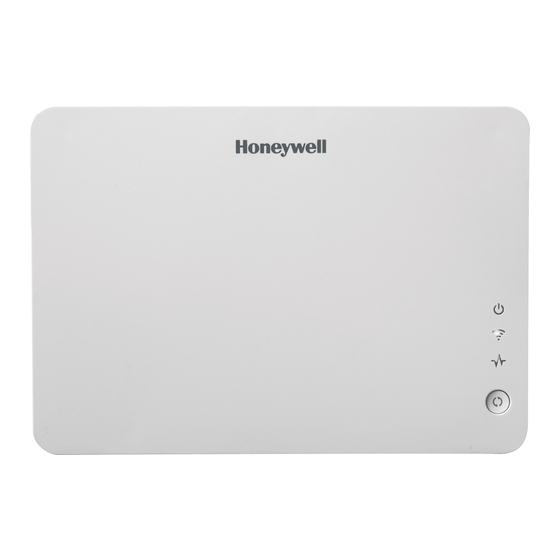
VAM (VISTA Automation Module) - Installation & Setup Guide
Introduction
VISTA Automation Module (herein referred to as "VAM") combines home automation and home security and is intended
for use with compatible VISTA
technology allowing VISTA installations to support Z-Wave devices.
The VISTA Automation Module also supports Remote Services for controlling Z-Wave devices and Scenes remotely from
an associated Total Connect™ account.
VAM is controlled using a web browser on a Wi-Fi enabled smart device such as a Tablet PC, laptop, Smartphone, etc.
DISPLAY NOTE: For optimum viewing of the screens and menus, the tablet's font size setting may need to be adjusted.
Make Wiring Connections
Connect VAM to the control panel's keypad data (ECP)
terminals using a standard 4-wire keypad connector harness.
VAM
REFER TO THE CONTROL PANEL'S INSTRUCTIONS
FOR MAXIMUM WIRE LENGTHS.
Wire Connections to the Control Panel
Verify that VAM and other connected devices do not exceed the
control's Aux Power output capability. If it does, use a
supplementary power supply as shown.
IMPORTANT: When VAM is powered from an auxiliary power
supply, always apply power to the control panel first and then
VAM. Failure to observe this sequence results in improper
operation of VAM and may result in an ECP Error indication.
POWER FROM SUPPLEMENTARY
POWER SUPPLY IF USED
SUPPLEMENTARY
+12 VDC
POWER SUPPLY
P/N AD12612
BLACK
BLACK
RED
GREEN
YELLOW
Supplementary Power Connections
\
CFS8DLVAM / 573F-VAM
®
series control panels. VAM includes a built-in web server, Wi-Fi
CONTROL PANEL
PC BOARD
TO
CONTROL PANEL
ECP TERMINALS
YELLOW
RED
BLACK
GREEN
4-WIRE CONNECTOR HARNESS
CONTROL
TERMINAL STRIP
AUX AUX
DATA
DATA
IN
OUT
pwr_supp_conn-011-V0
Mount the VAM
VAM is for indoor use only and should be mounted near the control
panel or a keypad connected to the control panel for ease of wiring.
VAM mounts to a wall surface by hanging on two screws. See the
diagram below.
• Leave the screw heads 1/8" above the wall surface.
• If necessary, drill a hole in the wall for the wire harness to pass
through.
• Connect the wire harness to the VAM before mounting.
2.54"
DRILL 3/16" DIA. HOLES 2 PLACES
Insert an SD/SDHC Memory Card
An SD card must be installed to receive automatic software
upgrades. The SD card can be left in the VAM. See Software
Upgrades section.
• Avoid touching the contacts on the card
• 4GB SD card supplied
• Supports up to 16GB SD Card
Insert the memory card (SD/SDHC Card) as shown.
INSERT
SD CARD
PLEASE GO TO THE BOTTOM OF
PAGE 7 FOR FCC / IC AGENCY
STATEMENTS.
®
capability, and Z-Wave
2.5"
MOUNTING SCREW
vam-004-V0
®
Advertisement
Table of Contents

Related Manuals for Honeywell VISTA Automation Module


Summary of Contents for Honeywell VISTA Automation Module
- Page 1 EXHIBIT 7-1 VAM (VISTA Automation Module) - Installation & Setup Guide Introduction VISTA Automation Module (herein referred to as “VAM”) combines home automation and home security and is intended for use with compatible VISTA ® series control panels. VAM includes a built-in web server, Wi-Fi ®...
-
Page 2: Front Panel Leds
Front Panel LEDs Set Up the WiFi Network To set up the WiFi network for VAM, you will need the following: • Wi-Fi enabled smart device ( Tablet PC, laptop, Smartphone, etc. • VAM SSID and WPA2 password (located on the VAM’s label) •... - Page 3 4. VAM automatically reboots after the device address is set. VAM, and enable Total Connect usage. Select Yes at the “using VISTA Automation Module” (Yes /No) prompt. You will Remote Services Option need the VAM MAC ID and CRC number, which can be found on a label on the back of the VAM or on its carton.
-
Page 4: Adding Z-Wave Devices
Refer to the Thermostat instructions. 1. Click Automation > Group Setup. 3. On the Honeywell thermostat select Thermostat; set the 2. Click the Add button and enter a Group Name > GO. “Time/Date” and follow the instructions in the thermostat Installation Guide for enrollment. - Page 5 Schlage Link Lever Lock Kwikset Smartcode Lever lock Save used to save options Kwikset Smartcode Deadbolt Lock Thermostats used when enabled Z-Wave Honeywell ECC TC Enable devices for Total Connect Wayne Dalton Zwave thermostat usage Trane Zwave Thermostat Appliance Accesses the Z-Wave...
-
Page 6: Software Upgrades
Software Upgrades Set Up Remote Access (Account Setup) Software upgrades may be available for this product. These Remote access lets the user access VAM’s menus directly via upgrades can be installed manually, or you can set VAM to notify the Internet when away from home. The home router must first you that an upgrade is ready and have it automatically installed. - Page 7 RF EXPOSURE Warning - The VISTA Automation Module (VAM) must be installed to provide a separation distance of at least 7.8 in. (20 cm) from all persons and must not be co-located or operating in conjunction with any other antenna or transmitter except in accordance with FCC multi-transmitter product procedures.
Need help?
Do you have a question about the VISTA Automation Module and is the answer not in the manual?
Questions and answers