
Related Manuals for Precision Rated Optics OLM-200 Series


Summary of Contents for Precision Rated Optics OLM-200 Series
- Page 1 OLM-200 Series Man Optical Loss Test Set (OLTS) OLM-201 A OLM-201 B OLM-202 A OLM-202 B Copyright © 2014 Precision Rated Optics. All rights reserved. Version 6.30.14...
-
Page 2: Table Of Contents
The information contained in this manual is believed to be accurate and reliable at the time of its creation. However, no responsibility is assumed by Precision Rated Optics for its use, nor for any infringements of patents or other rights of third parties that may result from its use. No license is implied or specified under any patent rights of Precision Rated Optics. -
Page 3: Introduction
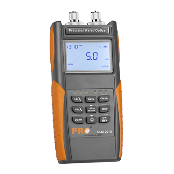
1. Introduction 1.1 General Description The OLM-200 Series Optical Loss Test Set (OLTS) combines a Power Meter and a either a two or three-wavelength Light Source, for optical fiber network installation and maintenance. With its large data storage capacity, it’s very convenient for field testing and transferring test results to a PC, through the USB interface. - Page 4 1. Introduction SPECIFICATIONS OLM-200 Series01A / OLM-200 Series02A / Item / Model No. OLM-200 Series01B OLM-200 Series02B Output Wavelength (nm) 1310/1550 1310/1490/1550 Connector Interchangeable FC /SC /ST for PC Modulation Frequencies (Hz) 270/1K/2K Light Source Output Power (dBm) -5dBm ± Stability Long-Term (8h) (dB) 0.1@1310/1550nm;...
-
Page 5: Safety Information
2. Safety Information Warning! ● Never look directly into optical outputs or a fiber while the equipment is on. Invisible light can easily cause injury to your eyes. ● Do not short-circuit the terminal of AC adapter / charger and the batteries. Excessive electrical current may cause personal injury due to fumes, electric shock, heat or equipment damage. -
Page 6: Preparing For Operation
3.3 AC/DC Adapter/Charger Operation There is a DC input jack on the bottom side of the OLM-200 Series device casing into which the output cable of the AC/DC adapter/charger is plugged. When the AC adapter is plugged in and the device is turned off, a “Charging”... -
Page 7: Getting Started
4.1 The Display and Control Panel Buttonpad The OLM-200 Series buttonpad can be divided into two parts. The first part is used to control the Light Source and the other is used to access the wide range of functions available for the Power Meter. - Page 8 4. Getting Started Function Description Light Source Port 1310nm, 1490nm and 1550nm (Two or three wavelengths, depending on device). 850/1300/1310/ Current wavelength being tested by the Optical Power Meter. 1490/1550/1625nm Reference value of the Optical Power Meter. 270Hz, 1kHz, 2kHz Modulated frequencies, as identified by Optical Power Meter.
-
Page 9: Usb Interface
4. Getting Started 4.2 USB Interface You can use the USB interface to connect the device with a PC and upload the stored data. There is a socket on the bottom side of the device next to the DC input jack. Use the supplied USB cable to connect the device to the USB interface of a PC. -
Page 10: Operating The Power Meter
5. Operating the Power Meter Button Definition in Button Definition in Button Definition in Data History” Mode “Testing” Mode “REF Setting” Mode 5.1 Operating in “Testing” Mode 5.1.1 Shifting the Wavelengths While in “Power Meter” Mode. Press the wavelength (Lambda) button to shift among the six wavelengths. Note: The Power Meter defaults to “Auto-Recognition”... - Page 11 5. Operating the Power Meter 5.1.2 Shifting the Measurement Devices of the Optical Power Meter The power meter defaults to the device of “dBm”. Press the “Device” button to shift from “dB” to “mW”. Note: 1) “dB” and “mW” are the units representing the absolute value of the tested power value. If the tested power value is less than 1mW while set to “mW”, the device will be shifted to “uW”...
- Page 12 5. Operating the Power Meter 5.1.3 Setting Reference Value on Optical Power Meter The reference value defaults to 0.00dBm when in Optical Power Meter mode. Push and hold the button for over 2 seconds to set the current optical power value as the reference value. Quickly pressing and releasing the button will display the current reference value.
-
Page 13: Operating In "Reference" Mode
5. Operating the Power Meter 5.2 Operating in “Reference” Mode Briefly press the “REF” button to check the reference value in the current wavelength. If there is no operation, the device will return to the testing mode automatically after two seconds. If you immediately press the button again, the device will enter the “editing”... - Page 14 5. Operating the Power Meter 5.2.2 Decreasing the Reference Value. Quickly press and release the button shown above to decrease the wavelength reference value in 0.1dB increments. Press and hold the button shown above to decrease the wavelength reference value in 1dB increments for the current wavelength.
- Page 15 5. Operating thethe Power Meter 5.2.3 Setting the Reference Value to Default Press the “Lambda” button to set the reference value in the current wavelength to “-5dBm”. Push and hold to set all the reference values (in all wavelengths) to “-5dBm”. Note: Setting the reference value to “-5dBm”...
-
Page 16: Operating In "Data Storage" Mode
5. Operating the Power Meter 5.2.5 Storing the Current Reference Setting Press to store the current reference setting. The stored data will be saved even when the device is turned off. The device will return to the measuring mode and automatically return to “dB” after storing the results. - Page 17 5. Operating the Power Meter 5.3.2 Checking the Data from 001 to 999 The current value is saved as number 001. Press the button briefly to check the stored value of record 002. Press and hold for over 2 seconds to check the stored value of higher numbered records. Note: If the data storage consists of less than 10 records, pressing and holding the storage button will revert the device back to the first stored record.
- Page 18 5. Operating the Power Meter 5.3.5 Deleting the Stored Data Quickly press and release the “PD” button to delete the current stored data displayed on the LCD. The next record will then be displayed on the LCD. If the data deleted is the only record stored, the device will automatically return to the measuring mode.
-
Page 19: Operating The Light Source
6. Operating the Light Source 6.1 Switching Wavelengths on the Light Source Module. The “Light Source” module defaults to “Off” when the user turns on the equipment. Press the wavelength LED to switch between 1310nm, 1490nm and 1550nm. If no LED is lighted, it means the device’s wavelength is turned “Off”. -
Page 20: Switching Between Modulated Wavelength And Constant Wavelength While In Light Source Mode
6. Operating the Light Source 6.2 Switching Between Modulated Wavelength and Constant Wavelength While in Light Source Mode While the Light Source is set on any wavelength: 1310nm, 1490nm or 1550nm, press the button shown above to select a modulation frequency of 270Hz, 1kHz or 2kHz. The LEDs will show you the frequency as well as the modulation frequency. -
Page 21: Switching On/Off The "Auto-Recognition" Mode Of The Light Source And Power Meter
6.3 Switching on/off the “Auto-Recognition” mode of the Light Source and Power Meter The wavelength “Auto-Recognition” feature is active if a pair of OLM-200 Series series devices are used as an OLTS and in “TWIN” mode. Press the “TWIN” button turn activate the “Auto-Recognition” mode. -
Page 22: Operating The Olm-200 Series "Data Manager" Software
Note: Before you attach the device to a PC using the supplied USB cable for the first time, you must install the OLM-200 Series “Data Manager” software from the CD included with your unit. System requirements Microsoft Windows 2000 / XP... -
Page 23: Installing "Data Manager" Software And Driver On Windows
7. OLM-200 Series “Data Manager” Software 7.2 Installing “Data Manager” Software & Driver on Windows Using the included “Data Manager” software is a very convenient way of storing and managing results using the OLM-200 Series. The operation is as follows: Place the disk in the CD-ROM drive. - Page 24 7. OLM-200 Series “Data Manager” Software 1.3. You will then enter the confirmation dialog. Click the "finish" button to finalize the installation. 2. Installation of Software 2.1. From the startup screen click "Installing Data Download Software". You will enter the Installation Wizard.
- Page 25 7. OLM-200 Series “Data Manager” Software 2.3 Enter the "Select Installation Folder" dialogue. The default installation path is "C:/Program Files/ Data Manager/Data Manager". If you wish to change the default installation path, you can click the "browse" button to change the path. After choosing your installation path, click the "Next"...
-
Page 26: Starting The Software
2. Or, after the installation, there will be an icon of “Data Manager” on the desktop. 7.4 Software Operation Connect the Optical Multimeter OLM-200 Series to your computer using the supplied USB cable and turn on the device. Click the "Data download " Button to download the test results. - Page 27 7. OLM-200 Series “Data Manager” Software To save the file as a Text file (*.txt) click the corresponding button. You can also save the file as an Excel document.(.xls) Note: The computer must have Microsoft Office Excel to save in Excel format.
-
Page 28: Uninstalling The Software
7. OLM-200 Series “Data Manager” Software You can also print the reports generated by the “Data Manager” software. 7.5 Uninstalling the Software The Data Manager provides “Auto-Uninstall” function. This allows for easy removal of all components, program groups and shortcuts of the software. -
Page 29: Basic Maintenance
8. Basic Maintenance ● When not in use and not charging, disconnect the AC/DC adapter/charger and cover the ports with the protective dust caps. ● It is recommended to clean the connector of the device often, as recommended by industry best practices. - Page 30 www.PrecisionRatedOptics.com Tel: (888) 545-1254 • Fax: (415) 358-4602 • Email: Sales@PrecisionRatedOptics.com...
- Page 31 www.PrecisionRatedOptics.com Tel: (888) 545-1254 • Fax: (415) 358-4602 • Email: Sales@PrecisionRatedOptics.com...
- Page 32 Precision Rated Optics, Inc. National Sales Office 2030 Blue Heron Circle Birmingham, AL 35242 Precision Rated Optics, Inc. Corporate Office Billing & Processing PO Box 877 Trexlertown, PA 18087 Precision Rated Optics, Inc. Product Distribution Center Manufacturing & Testing 9999 Hamilton Blvd...
Need help?
Do you have a question about the OLM-200 Series and is the answer not in the manual?
Questions and answers