Table of Contents
Advertisement
Quick Links
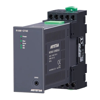
INSTRUCTION MANUAL
MODBUS I/O MODULE
(4 points, RMS sensing, clamp-on current sensor input)
BEFORE USE ....
Thank you for choosing M-System. Before use, please check
contents of the package you received as outlined below.
If you have any problems or questions with the product,
please contact M-System's Sales Office or representatives.
■ PACKAGE INCLUDES:
Modbus I/O module .............................................................(1)
Terminal resistor (110Ω, 0.25W) ........................................(1)
■ MODEL NO.
Confirm Model No. marking on the product to be exactly
what you ordered.
■ INSTRUCTION MANUAL
This manual describes necessary points of caution when
you use this product, including installation, connection and
basic maintenance procedures.
For information on Modbus specification, refer to the Mod-
bus Protocol Reference Guide (EM-5650).
This manuals is downloadable at M-System's web site
(https://www.m-system.co.jp).
POINTS OF CAUTION
■ CONFORMITY WITH EU DIRECTIVES
• The equipment must be mounted inside the instrument
panel of a metal enclosure.
• The actual installation environments such as panel con-
figurations, connected devices, connected wires, may af-
fect the protection level of this unit when it is integrated
in a panel system. The user may have to review the CE
requirements in regard to the whole system and employ
additional protective measures to ensure the CE conform-
ity.
■ POWER INPUT RATING & OPERATIONAL RANGE
• Locate the power input rating marked on the product
and confirm its operational range as indicated below:
24V DC rating: 24V ±10%, approx. 90mA
■ GENERAL PRECAUTIONS
• Before you remove the terminal block or mount it, turn off
input signals for safety.
■ ENVIRONMENT
• Indoor use.
• When heavy dust or metal particles are present in the
air, install the unit inside proper housing with sufficient
ventilation.
• Do not install the unit where it is subjected to continuous
vibration. Do not subject the unit to physical impact.
• Environmental temperature must be within -10 to +55°C
(14 to 131°F) with relative humidity within 10 to 90% RH
in order to ensure adequate life span and operation.
■ WIRING
• Do not install cables close to noise sources (relay drive
5-2-55, Minamitsumori, Nishinari-ku, Osaka 557-0063 JAPAN
Phone: +81(6)6659-8201 Fax: +81(6)6659-8510 E-mail: info@m-system.co.jp
MODEL
cable, high frequency line, etc.).
• Do not bind these cables together with those in which
noises are present. Do not install them in the same duct.
■ AND ....
• The unit is designed to function as soon as power is sup-
plied, however, a warm up for 10 minutes is required for
satisfying complete performance described in the data
sheet.
R10M-CT4E
EM-6247 P. 1 / 7
Advertisement
Table of Contents

Related Manuals for M-system R10M-CT4E


Summary of Contents for M-system R10M-CT4E
- Page 1 • Do not bind these cables together with those in which noises are present. Do not install them in the same duct. Thank you for choosing M-System. Before use, please check contents of the package you received as outlined below.
- Page 2 FE1 Power grounding Input 1-L SLD Shield Input 2-L Input 3-L Unused Input 4-L 24V Power supply 24V DC Unused Power supply 0V DC EM-6247 P. 2 / 7 5-2-55, Minamitsumori, Nishinari-ku, Osaka 557-0063 JAPAN Phone: +81(6)6659-8201 Fax: +81(6)6659-8510 E-mail: info@m-system.co.jp...
- Page 3 Depending on data mode and parity bit setting, data bit and stop bit are as following. DATA MODE PARITY BIT DATA BIT STOP BIT None Modbus-RTU Odd or Even None Modbus-ASCII Odd or Even EM-6247 P. 3 / 7 5-2-55, Minamitsumori, Nishinari-ku, Osaka 557-0063 JAPAN Phone: +81(6)6659-8201 Fax: +81(6)6659-8510 E-mail: info@m-system.co.jp...
- Page 4 A) Push down the lower slider using a minus screwdriver. B) Pull out the lower part of the unit. C) Remove the upper part of the unit from the DIN rail. EM-6247 P. 4 / 7 5-2-55, Minamitsumori, Nishinari-ku, Osaka 557-0063 JAPAN Phone: +81(6)6659-8201 Fax: +81(6)6659-8510 E-mail: info@m-system.co.jp...
- Page 5 CT INPUT 1 To other Modbus devices CT INPUT 2 24V DC CT INPUT 3 POWER CT INPUT 4 INPUT CONNECTION SOURCE CLAMP-ON SENSOR LOAD EM-6247 P. 5 / 7 5-2-55, Minamitsumori, Nishinari-ku, Osaka 557-0063 JAPAN Phone: +81(6)6659-8201 Fax: +81(6)6659-8510 E-mail: info@m-system.co.jp...
- Page 6 Recommended manufacturer: Japan Solderless Terminal MFG.Co.Ltd, Nichifu Co.,ltd (Solderless terminals with insulation sleeve do not fit) Applicable wire size: 0.25 to 1.65 mm 3max 4min 3.2 dia. (mm) EM-6247 P. 6 / 7 5-2-55, Minamitsumori, Nishinari-ku, Osaka 557-0063 JAPAN Phone: +81(6)6659-8201 Fax: +81(6)6659-8510 E-mail: info@m-system.co.jp...
- Page 7 Data error status is indicated by 1 bit. 0: OFF 1: ON LIGHTNING SURGE PROTECTION M-System offers a series of lightning surge protector for protection against induced lightning surges. Please contact M-System to choose appropriate models EM-6247 P. 7 / 7 5-2-55, Minamitsumori, Nishinari-ku, Osaka 557-0063 JAPAN Phone: +81(6)6659-8201 Fax: +81(6)6659-8510 E-mail: info@m-system.co.jp...
Need help?
Do you have a question about the R10M-CT4E and is the answer not in the manual?
Questions and answers