Advertisement
Quick Links
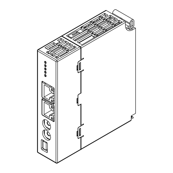
Remote I/O R30 Series
NETWORK MODULE
(CC-Link IE Field network)
Functions & Features
• Interchanges analog or discrete I/O signals with the
filedbus (CC-Link IE Field network)
• Combined with R3 Series I/O modules
25
[.98]
110
[4.33]
98 [3.86]
mm [inch]
MODEL: R30NCIE1[1]
ORDERING INFORMATION
• Code number: R30NCIE1[1]
Specify a code from below for [1].
(e.g. R30NCIE1/Q)
• Specify the specification for option code /Q
(e.g. /C01)
[1] OPTIONS
blank: none
/Q: With options (specify the specification)
SPECIFICATIONS OF OPTION: Q
COATING (For the detail, refer to M-System's web site.)
/C01: Silicone coating
/C02: Polyurethane coating
/C03: Rubber coating
https://www.m-system.co.jp/
CAUTION
• The internal bus communication period for R3 series I/O
modules installed on the R30EBS is as follows.
Internal bus communication period = 6 msec. × number of
I/O module + 10 msec. (Data update period of main CPU)
Example: Four R3 I/O modules
6 msec. × 4 + 10 msec. = 34 msec.
Even when the R30EBS is mounted to the R30BS, the
internal bus communication period of R30 series is kept to
approx. 1 msec.
RELATED PRODUCTS
• PC configurator software (model: R30CFG)
• PC configurator software (model: R3CON)
Downloadable at M-System's web site.
For connecting to PC, use commercially available Mini-B
type USB cable. (provided by user)
• R3 series I/O modules (except R3-TC2 and R3S-CM2A)
GENERAL SPECIFICATIONS
Connection
CC-Link IE Field: RJ-45 connector
Internal bus: Via the Installation Base (model: R30BS)
Internal power: Via the Installation Base (model: R30BS)
Isolation: CC-Link IE Field to internal bus or internal power
Input type & range:
R30 series I/O module: PC configuration software (model:
R30CFG)
R3 series I/O module: PC configuration software (model:
R3CON)
Network address: PC configuration software (model:
R30CFG)
Internal bus communication cycle: Approx. 1 msec.
Status indicator: RUN, RD, SD, D LINK, ERR, L ER, LINK
(Refer to the instruction manual.)
CC-Link IE Field COMMUNICATION
Protocol: IEEE 802.3
Transmission type: 1000BASE-T
Communication speed: 1 Gbps
Network cable: Cable conformed to CC-Link IE Field
Double shielded twist pair cable (CAT5e)
RJ-45 connector
Network topology: Line, star and ring
Max. number stations: 120 (Total slave station)
(Number of max. connectable slaves may vary depending
on the master module. Refer to the instruction manual of
the master module)
Max. station-to-station distance: 100 m
Station type: Remote device station
Link device: RX/RY 128 points, RWw/RWr 64 points
R30NCIE1 SPECIFICATIONS
MODEL: R30NCIE1
ES-9020 Rev.6 Page 1/7
Advertisement

Related Manuals for M-system R30 Series


Summary of Contents for M-system R30 Series
- Page 1 6 msec. × 4 + 10 msec. = 34 msec. filedbus (CC-Link IE Field network) Even when the R30EBS is mounted to the R30BS, the • Combined with R3 Series I/O modules internal bus communication period of R30 series is kept to approx. 1 msec. [.98] RELATED PRODUCTS •...
-
Page 2: Installation
MODEL: R30NCIE1 (Number of points summation of I/O module for R30 series and R3 series) NetWork No.: 1 to 239 (factory default: 1) INSTALLATION Current consumption: 160 mA Operating temperature: -10 to +55°C (14 to 131°F) Storage temperature: -20 to +65°C (-4 to +149°F) - Page 3 I/O module has space, data is transmitted close to HOST PC/PLC. Station type: Remote device station Link device: RX/RY 128points, RWw/RWr 64points (Points are total of R30 series and R3series module) E.g. I/O data is assigned as shown below in the case of following configuration. BASE SLOT NO.
- Page 4 RX(n+0)8 to A, RX(n+0)C to F are not used. • Module Status RX(n+1)0 to RX(n+1)F indicate whether individual I/O modules of R30 series are mounted or not . RX(n+2)0 to RX(n+2)F indicate whether individual I/O modules of R3 series are mounted or not.
- Page 5 32-bit binary data is used for accumulated counts, encoder positions and active energy. Lower 16 bits are allocated from the lowest address to higher ones, higher 16 bits in turn. Lower 16 bits Higher 16 bits R30NCIE1 SPECIFICATIONS ES-9020 Rev.6 Page 5/7 https://www.m-system.co.jp/...
- Page 6 ■ 16-POINT DISCRETE DATA (models: R30XN16A, R30YN16x, etc.) Input 1 (Output 1) Input 2 (Output 2) Input 3 (Output 3) Input 16 (Output 16) 0 : OFF 1 : ON EXTERNAL DIMENSIONS unit: mm [inch] 25 [.98] 98 [3.86] R30NCIE1 SPECIFICATIONS ES-9020 Rev.6 Page 6/7 https://www.m-system.co.jp/...
- Page 7 RJ-45 MODULAR JACK PC CONFIGURATOR USB CONNECTOR CONNECTOR Regarding CN1 and CN2 of RJ-45 connector for CC-Link IE Field network, there is no restriction for connection order. Specifications are subject to change without notice. R30NCIE1 SPECIFICATIONS ES-9020 Rev.6 Page 7/7 https://www.m-system.co.jp/...
Need help?
Do you have a question about the R30 Series and is the answer not in the manual?
Questions and answers