KONIG+NEURATH TALO.S Instructions Manual
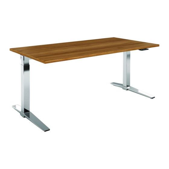
Height-adjustable lift desks
Hide thumbs
Also See for TALO.S:
- Operating instructions manual (52 pages) ,
- Assembly instructions manual (38 pages) ,
- Operating instructions manual (64 pages)
Table of Contents
Advertisement
Available languages
Available languages
Quick Links
Advertisement
Table of Contents

Related Manuals for KONIG+NEURATH TALO.S


Summary of Contents for KONIG+NEURATH TALO.S
- Page 1 TALO.S Höhenverstellbare Lift-Tische Vor Inbetriebnahme unbedingt lesen! Height-adjustable lift desks Please read the following instructions carefully! Bedienungs- und Montageanleitung Operating and assembly instructions...
-
Page 3: Table Of Contents
Inhalt Vorwort Anwendungsbereich, Transport Wichtige Sicherheitshinweise Nutzlast Entfernung der Transportsicherung Höhenverstellung des Tisches Nutzlasteinstellung (optional) Schiebeplatte Vertikale Kabelführung mit Kabelkette Montage Druckerablage Montage CPU-Halterung 11-12 Montage Rückwandverblendung Montage Plattenansteckelement Montage Fly By-Paneel Montage Tischpaneel (in Aufbau– und Klemmadapter) Montage Reling Montage Anbauelemente (werkzeuglos) Montage Steckdosenbox Belastbarkeit Anbauelemente... -
Page 5: Vorwort
Vorwort Sehr geehrte Kundin, sehr geehrter Kunde, Sie haben sich für ein Markenprodukt aus dem Hause König + Neu- rath entschieden. Damit dieses Möbel zu Ihrer Zufriedenheit funktio- niert, lesen Sie bitte diese Anweisungen vor Inbetriebnahme aufmerk- sam durch und beachten Sie die angegebenen Sicherheitshinweise. -
Page 6: Anwendungsbereich, Transport
Anwendungsbereich Die TALO.S Lift-Tische sind Arbeitstische, bzw. Bildschirm- arbeitstische für sitzenden und stehenden Tätigkeit im Büro. Sie sind nicht für den Einsatz im Werkstatt- oder Lagerbereich geeignet. Sie sind nicht für den Einsatz in Feuchträumen ge- eignet. Transport Bitte heben oder tragen Sie den Tisch nicht an der Tisch- platte, sondern an dem Plattenrahmen. -
Page 7: Wichtige Sicherheitshinweise
Wichtige Sicherheitshinweise Der Aufbau und die Bedienung des TALO.S Lift-Tisches muss gemäß dieser Montage- und Bedienungsanleitung erfolgen, sonst besteht akute Verletzungsgefahr. Das 2-Säulen-Liftgestell ist ausschließlich für den Verwen- dungszweck als ergonomische Verstellmöglichkeit bei Schreibtischen, entsprechend den angegebenen Gewich- ten und Maßen, in dieser Montageanleitung geeignet. -
Page 8: Nutzlast
Nutzlast Die Tische sind bei Auslieferung komplett montiert. Die folgenden Schritte erläutern Ihnen die Entfernung der Transportsicherung, die Bedienung des Lift-Tisches und die Montage der Anbauteile. Der Tisch ist im Anlieferzustand für eine Nutzlast von 20 oder 40 ± 10 kg ausgelegt. Die Nutzlast ist im Hinweisfeld unter der Tischplatte an der Längstraverse angegeben. -
Page 9: Entfernung Der Transportsicherung
Entfernung der Transportsicherung (a) Abdeckkappen entfernen. Linke Hand mit leichtem Druck als zusätzliche Sicherung auf die Tischplatte legen. (b) Mit der rechten Hand die Splintsicherungen entfernen. Für eventuell weitere Transporte die Splintsicherungen am Clip des Gestells aufbewahren. Achtung ! Handauslösung nur betätigen, wenn das vorgegebene Gewicht auf dem Gestell steht. -
Page 10: Höhenverstellung Des Tisches
Höhenverstellung des Tisches Nutzlast an und auf den Tisch bringen (Bildschirm, CPU, etc). Die Nutzlast muss mit ± 10 kg mit der angegebenen Nutzlast im Hinweisfeld übereinstimmen. Achtung ! Handauslösung nur betätigen, wenn das vorgegebene Gewicht auf dem Gestell steht. Um die Höhe des Tisches zu verstellen, wird eine Hand mit leich- tem Druck auf die Tischplatte gelegt, mit der anderen Hand der Auslösegriff betätigt und der Tisch in die gewünschte Position... -
Page 11: Nutzlasteinstellung (Optional)
Nutzlasteinstellung (optional) Achtung: Bei Auslieferung ist keine Nutzlast eingestellt! = hohe Nutzlast = geringe Nutzlast max.100 Umdrehungen... -
Page 12: Schiebeplatte
Schiebeplatte (a) Zum Entriegeln der Schiebeplatte, Griff nach unten ziehen und Platte nach vorne schieben. (b) Der Kabelkanal wird sichtbar, die Elektrifizierung des Tisches kann nun erfolgen. Vertikale Kabelführung mit Kabelkette (c) Kabelblende von innen an Außenrohr des Seitenteils festkleben. (Unterkante Kabelblende sitzt auf Ausleger.) (d) Kabelkettenanschluss auf Ausnehmung in Kabelblende stecken. -
Page 13: Montage Druckerablage
Montage Druckerablage (a) Konsole an Halteblech montieren (SW 4), Druckerplatte auf Konsole befestigen. (b) Vierkant in Plattenrahmen stecken. Verbindungsklammer von unten durch Rahmen mit Vierkant verschrauben (SW 5). (c) Halteblech an Verbindungsklammer schrauben (SW 4). (d) Tische mit Tischklappe: Vor Montage, Unterteil des Platten- beschlags entfernen. -
Page 14: Montage Cpu-Halterung
Montage CPU-Halterung (a) CPU-Halterung an Halteblech montieren (SW 3). (b) Vierkant in Plattenrahmen stecken. Verbindungsklammer von unten durch Rahmen mit Vierkant verschrauben (SW 5). (c) Halteblech an Verbindungsklammer montieren (SW 4). (d) Tische mit Tischklappe: Vor Montage, Unterteil des Platten- beschlags entfernen. - Page 15 Tische mit Nutzlasteinstellung Bei CPU Anbau rechts außen/innen bitte folgendes beachten: Anbau rechts außen CPU-Halterung versetzen Anbau rechts innen CPU-Halterung versetzen...
-
Page 16: Montage Rückwandverblendung
Montage Rückwandverblendung (a) Abdeckstopfen aus Rahmenkonsole ziehen. Gewindeplatte in Konsole einlegen. (b) Rückwandhalter von unten durch Konsole mit Gewindeplatte verschrauben (SW 5). Rückwandverblendung an Rückwand- halter montieren (SW 4). Abdeckstopfen in Konsole setzen. -
Page 17: Montage Plattenansteckelement
Montage Plattenansteckelement (a) Abdeckstopfen entfernen, Konsolen in Rahmenkonsolen schieben. (b) Seitlich verschrauben (SW 5). (c) Platte 1 auf Konsolen positionieren und zur Tischplatte aus- richten, von unten leicht anschrauben (ohne Abb.). Mit Gewindestiften 2 (SW 4) kann das Element zur Tischplatte justiert werden, Gewindestift 3 (SW 3) dient zur Neigungsver- stellung. -
Page 18: Montage Fly By-Paneel
Montage Fly By-Paneel (a) Abdeckstopfen entfernen. (b) Halteblech des Fly By-Paneels in Rahmenkonsole stecken. (c) Seitlich mit je drei Schrauben (SW 5) befestigen. innen... -
Page 19: Montage Tischpaneel (In Aufbau- Und Klemmadapter)
Montage Tischpaneel (a) Abdeckung entfernen und Fenster freimachen. (b) Abdeckung auf Tischadapter setzen und Klemmadapter in Tischadapter stecken, Gewindestift (SW 3) festziehen. (c) Paneel einsetzen und seitlich ausrichten, Schraube auf Adap- terrückseite anziehen (SW 4). (d) Klemmadapter auf Tischplatte schieben (bei Tischen ohne Adapterausschnitte) und untere Stellschraube (SW 4) fest- drehen. -
Page 20: Montage Reling
Montage Reling (a) Abdeckung entfernen. Relingprofil mit Adapter verschrauben (SW 5). Achtung: Vormontierte Adapter müssen demontiert werden! (b) Konsolenabdeckung entfernen. Adapter auf Konsole montieren (SW 5). (c) Kabelclip in Profilnut der Reling eindrehen. -
Page 21: Montage Anbauelemente (Werkzeuglos)
Montage Anbauelemente (a) Anbauelement in Organisationsnut einhängen. (b) Aufsatz-Anbauelement auf Tischpaneel stecken. Belastbarkeitsangaben auf Seite 20 beachten! (c) Bei Tischpaneelen mit ein- oder beidseitiger Organisations- nut ist das Aufstecken eines Aufsatz-Anbauelementes nicht möglich. -
Page 22: Montage Steckdosenbox
Montage Steckdosenbox (a) Abdeckung entfernen und Fenster freimachen. (b) Abdeckung auf Tischadapter setzen und Steckdosenbox in Tischadapter stecken, Gewindestift (SW 3) festziehen. (c) Steckdosenzwinge auf Tischplatte schieben und untere Ge- windestifte (SW 4) festziehen. Steckdosenbox auf Zwinge schieben und einklipsen. (d) Tischpaneel: Nutensteine in Organisationsnut einsetzen und Adapterblech montieren (SW 4). -
Page 23: Belastbarkeit Anbauelemente
Sicherheitshinweise Belastbarkeit der Anbauelemente: Ordnerablage einseitig Achtung: Maximale Belastbarkeit der Organisationsnut = 25 kg max. 10 kg Halterung mit Ablageschale Ordnerablage Ablageschale max. 10 kg max. 5 kg max. 5 kg/Ablageschale Monitorarm: Belastung max. 8 kg Max. 3 Monitorarme pro Monitorarm pro Reling möglich! Max. -
Page 24: Pflege- Und Reinigungshinweise
Pflege- und Reinigungshinweise Kunststoff- und Metalloberflächen: Oberfläche mit einem Staubtuch reinigen. Bei Verschmutzungen warmes Wasser verwenden und / oder einen milden Reiniger, da- nach trocken wischen. Achtung: Keine scheuernden Reinigungsmittel verwenden ! Diese können zu bleibenden, optischen Schäden führen. Echtholzoberflächen: Oberfläche mit einem Staubtuch reinigen. -
Page 25: Anhang
Um Fehlfunktionen zu vermeiden, dürfen alle Reparaturen nur von Fachpersonal durchgeführt werden. Informieren Sie bitte den K+N Kundendienst ! Wartung Der Lifttisch ist wartungsfrei. Entsorgung Der höhenverstellbare Lifttisch der Serie TALO.S ist nach gültigen Richtlinien und Vorschriften umweltgerecht zu entsorgen. Kundendienst : Telefon 06039/483-0... -
Page 27: Introduction
Introduction Dear customer, You have chosen a quality product from König + Neurath. To ensure that your furniture performs to your complete satisfaction, please read the following instructions carefully, and take note of the safety guide- lines. -
Page 28: Area Of Application, Transport
Area of application The TALO.S lift desks are workplace desks or monitor desks suited to working while sitting and standing in the office area. The desks are not suitable for use in the workshop or warehouse, not in wet areas. -
Page 29: Important Safety Information
Important safety information The TALO.S lift desk must be assembled and used according to these operating and assembly instruc- tions, otherwise there is a risk of serious injury. The 2-column lift frame is exclusively designed for use as an ergonomic adjustment option for desks, com- plying with the weights and dimensions as stated in these assembly instructions. -
Page 30: Payload
Payload The desks are supplied fully assembled. The following steps explain how to remove the transport lock, how to operate the lift desk and how to fit the accessories and extensions. The desk is supplied for use with a payload of 20 or 40 ± 10 kg. The payload is stated on the information label underneath the desk top on the main beam. -
Page 31: Removal Of The Transport Clip (Cotter Pin)
Removal of the transport clip (cotter pin) (a) Remove the end cap on the right-hand side. Place your left hand on the desk top and apply slight pressure as an additional safety measure. (b) Remove the cotter pin with your right hand. Keep the cotter pin safe by attaching it the clip on the frame for any further transport requirements. -
Page 32: Height Adjustment Of The Desk
Height adjustment of the desk Put the payload onto the desk (monitor, CPU, etc). The payload must be within ± 10 kg of the payload stated on the information label. Caution ! Only operate the manual release if the spe- cified weight is being supported by the frame. -
Page 33: Payload Adjustment (Optional)
Payload adjustment (optional) Note: On delivery there is no payload adjusted. = low payload = high payload max.100 revolutions... -
Page 34: Sliding Top
Sliding top (a) To unlock the sliding top, push the handle down and pull the desk top to the front. (b) The cable tray is now visible and the desk can be supplied with power and data. Vertical cable management with cable chain (c) Stick the cable trim to the inside of the leg. -
Page 35: Fitting The Printer Tray
Fitting the printer tray (a) Fit the console to the retaining plate (SW 4) and attach the printer shelf to the console. (b) Insert the square shaft into the desk top frame. Screw the connecting clamp to the square shaft from underneath through the frame (SW 5). -
Page 36: Fitting The Cpu Holder
Fitting the CPU holder (a) Attach CPU holder to the retaining plate (SW 3). (b) Insert square shaft into the desk top frame. Screw the connecting clamp to square shaft from underneath through the frame (SW 5). (c) Screw the retaining plate to the connecting clamp (SW 4). (d) Desk top with desk flap: Before assembly, remove lower part of the fitting. - Page 37 Desks with payload adjustment Please note the following when mounting CPU holder on the right side: right-hand outside displace CPU holder right-hand inside displace CPU holder...
-
Page 38: Fitting The Modesty Panel
Fitting the modesty panel (a) Remove the end caps from the frame console. Place the threaded plate into the console. (b) Screw the modesty panel bracket to the plate from under- neath through the console (SW 5). Fit the modesty panel onto the modesty panel bracket (SW 4). -
Page 39: Fitting The Briefcase Extension
Fitting the briefcase extension (a) Remove the end caps from the frame console (not illustrated). Slide the briefcase extension support into the frame console. (b) Screw them together from the side (SW 5). (c) Position top 1 to the consoles, fit them together from under- neath, tighten screws slightly (not illustrated). -
Page 40: Fitting The Fly-By Screen
Fitting the fly-by screen (a) Remove end caps. (b) Insert the retaining plate for the fly-by screen into the frame console. (c) Screw in place from the side (SW 5). inside... -
Page 41: Fitting The Desk Screen (In 3Rd Level And Clamp Adapters)
Fitting the desk screen (a) Remove cover and snap off the central part. (b) Attach cover and insert clamp adapter into desk adapter, tighten grub screw (SW 3). (c) Insert the screen and align it laterally. Tighten the screw on rear of adapter (SW 4). (d) Slide clamp adapter onto desk top and insert screen into adapter. -
Page 42: Fitting The Railing
Fitting the railing (a) Remove cover. Mount profile on the adapter (SW 5). Note: pre-assembled adapter must be disassembled! (b) Remove end caps. Mount adapter on the bracket (SW 5). (c) Insert cable clip into profile groove. -
Page 43: Fitting The Accessories (Tool-Free)
Fitting the accessories (a) Accessories hook into the organiser groove. (b) 3rd-level accessories slot onto the desk screen from above. Please note maximum load specifications on page 42. (c) Note: if desk screens have an organiser groove on one or both sides, it is not possible to use 3rd-level accessories. -
Page 44: Fitting The Power Box
Fitting the power box (a) Remove cover and snap off the central part. (b) Attach cover and insert power box into the desk adapter, tighten the grub screw (SW 3). (c) Slide power box clamp onto desk top. Tighten from beneath with grub screws (SW 4). -
Page 45: Max.load For Desk Accessories
Safety information Maximum load for accessories Filing tray one side Note: maximum load for organiser groove = 25 kg max. 10 kg Binder shelf Filing tray Bracket with filing tray max. 10 kg max. 5 kg max. 5 kg/filing tray Monitor arm max. -
Page 46: Care And Cleaning Information
Care and cleaning information Plastic-coated and metal surfaces: Clean the surface with a duster. Use warm water and / or a mild cleaner to remove marks, then wipe dry. Caution: Do not use abrasive cleaners! This can cause permanent visible damage. Natural wood finishes: Wipe the surface with a duster. -
Page 47: Appendix
To prevent malfunctions, any repairs may only be made by specialists. Please notify K+N customer service! Maintenance The lift desks are maintenance-free. Disposal The TALO.S height-adjustable lift desks must be disposed in accordance with the valid directives and regulations. Customer service: Telephone +49 (0)6039 483-0... - Page 48 Deutschland König + Neurath AG Büromöbel-Systeme Industriestraße 1-3 61184 Karben Tel.: +49 (0)6039 483-0 Fax: +49 (0)6039 482-214 e-mail: info@koenig-neurath.de www.koenig-neurath.de Great Britain K + N International (Office Systems) Ltd 52 Britton Street London EC1M 5UQ Tel.: +44 (0)20 74909340 Fax: +44 (0)20 74909349 e-mail: info@koenig-neurath.co.uk www.koenig-neurath.co.uk...
Need help?
Do you have a question about the TALO.S and is the answer not in the manual?
Questions and answers