Advertisement
Quick Links
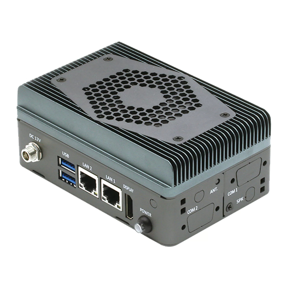
Quick Installation Guide
PICO-APL4-SEMI
This document will guide you through
the basic installation process for your
new PICO-APL4-SEMI.
PICO-APL4-SEMI
Packing
1
Item
1
PICO-APL4 Board
2
Top Chassis
3
Bottom Chassis
4
Cooler
5
Accessory kits
Power Button Cable x1
Screw.M3. Black x8pcs
Screw.M3 Nickel x4pcs
2
Description
3
4
Remark/PN
MB
M17KBU4000
M17KBU4010
17592SEMI1
1709100109
S1D3004031
S1D5106010
5
Advertisement

Subscribe to Our Youtube Channel
Related Manuals for Asus AAEON PICO-APL4-SEMI


Summary of Contents for Asus AAEON PICO-APL4-SEMI
- Page 1 Quick Installation Guide PICO-APL4-SEMI This document will guide you through the basic installation process for your new PICO-APL4-SEMI. PICO-APL4-SEMI Item Description Remark/PN PICO-APL4 Board Top Chassis M17KBU4000 Bottom Chassis M17KBU4010 Cooler 17592SEMI1 Accessory kits Power Button Cable x1 1709100109 Screw.M3. Black x8pcs S1D3004031 Screw.M3 Nickel x4pcs S1D5106010...
- Page 2 Install Guide Steps PICO-KBU4-SEMI Quick Installation Guide Step 1: On the thermal assembly, remove the plastic covering as shown. Step 2: Place the top chassis onto the thermal assembly. Note the orientation of the chassis with the thermal assembly. Secure with four black screws. Step 3: On the PICO-APL4 board, remove the nut and washer from the power input port.
- Page 3 Step 7: Thread the power button cable through the hole for the power button. Plug the cable into the front panel connector (the 2nd connector from the front, CN3 in user manual), then gently push the power button in until it is secure (you will hear a ‘snap’). NOTE: Be careful not to tangle the power button cable with the CMOS battery cable.
Need help?
Do you have a question about the AAEON PICO-APL4-SEMI and is the answer not in the manual?
Questions and answers