
Related Manuals for Sices ATS LOGICA


Summary of Contents for Sices ATS LOGICA
- Page 1 Filename: Use and Maintenance Manual Rev. 01 Date: 01/03/2016 Product: ATS LOGICA Control Panel Model with ATS115...
- Page 2 8. Transport, storage and decommissioning ..............36 9. Faults and possible causes (see also ATS115 manual) ........... 37 10. How to ask for assistance ..................39 11. Our range: overall dimensions ................. 40 Use and Maintenance Manual ATS LOGICA CONTROL PANEL with ATS115...
- Page 3 SICES is pleased to thank you for purchasing our ATS LOGICA Automatic Transfer Switch Panel. This Control Panel is the result of the design, the selection of the best components, the careful assembly and the strict test to which all SICES products are submitted.
- Page 4 The Control Panel is intended to be used only to the purpose for which it has been designed. Any other use is considered improper and therefore dangerous. Use and Maintenance Manual ATS LOGICA CONTROL PANEL with ATS115...
- Page 5 If any doubt persists after reading the following paragraphs and attachments, please do not hesitate to contact the SICES Technical Service. All operations must be always performed in compliance with the safety regulations.
- Page 6 The installer must provide the installation of all the necessary equipment aimed at guarantee a safe and correct operation of the system in which the ATS LOGICA Control Panel and Genset are installed (e.g. coordination of the protections against direct and indirect contacts).
- Page 7 In order to adjust the Control Panel to the different AC voltage level, it is necessary to carry out some operations related to both control panel internal connections (HW) and ATS115 controller parameters modifications (SW). Use and Maintenance Manual ATS LOGICA CONTROL PANEL with ATS115...
- Page 8 WARNING: All voltage switch operations have to be carried out before the operation start, with absence of voltage. THE CONTROL PANEL IS PRODUCED AND CONFIGURED FOR THREE-PHASE + NEUTRAL 400V OPERATIONS. Use and Maintenance Manual ATS LOGICA CONTROL PANEL with ATS115...
- Page 9 Remove the protection panel and disconnect the Disconnect coil supply connector. changeover switch connector. KBG = ABB KBG = TECHNOELECTRIC (Lower side) (Upper side) For the voltage change (size 45÷125A) please contact SICES Sales Department. Use and Maintenance Manual ATS LOGICA CONTROL PANEL with ATS115...
- Page 10 WARNING: it is advisable to move one cable at a time in order to avoid inverting the sequence with the other cables. CHECK THE VOLTAGE ON THE SWITCH AND POWER SUPPLY CONNECTORS (OPTIONAL). Use and Maintenance Manual ATS LOGICA CONTROL PANEL with ATS115...
- Page 11 NOTE: for the side by side “X1” bar, the red ringed cable is connected to the terminals with an “even number” (right). WARNING: it is advisable to move one cable at a time in order to avoid inverting the sequence with the other cables. Use and Maintenance Manual ATS LOGICA CONTROL PANEL with ATS115...
- Page 12 Arrow keys for the navigation and CONFIGURATION Area Arrow keys for the modes Buttons for the modes OFF/AUTO/MAN OFF / AUTO / MAN Set the parameters by means of the configuration keyboard. Use and Maintenance Manual ATS LOGICA CONTROL PANEL with ATS115...
- Page 13 OFF/AUTO/MAN Area Using the arrow keys put the device on CONFIGURATION Area Using the arrow keys select the page 03 PROGRAM Using the arrow keys select the submenu: 1 System Use and Maintenance Manual ATS LOGICA CONTROL PANEL with ATS115...
- Page 14 Press ESC in order to go back to the main menu and to browse through pages. The parameters that must be changed for the voltage modification are all listed in the submenu 1-System. Use and Maintenance Manual ATS LOGICA CONTROL PANEL with ATS115...
- Page 15 P.0202 = 400 4) Operating voltage 440V: a. P.0102 = 440 b. P.0202 = 440 5) Nominal frequency 50Hz: a. P.0301 = 50 6) Nominal frequency 60Hz: a. P.0301 = 60 Use and Maintenance Manual ATS LOGICA CONTROL PANEL with ATS115...
- Page 16 The ATS LOGICA Control Panel is a device that allows to supply alternatively a system that uses two different and independent sources of energy, which usually are: Source A (Mains) and/or Source B (Genset). According to the nominal current, besides the panel circuits, the switch takes place by means of: 1) 2 four-pole contactors which are electrically and mechanically interlocked (45 - 125A);...
- Page 17 WITH INDICATOR ON “0” WITH INDICATOR ON “I” (TWO) THE LOAD IS (ONE) THE LOAD IS SUPPLIED (ZERO) THE LOAD IS NOT SUPPLIED BY THE MAINS SUPPLIED BY ANY SOURCE BY THE GENSET Use and Maintenance Manual ATS LOGICA CONTROL PANEL with ATS115...
- Page 18 WARNING: Check the cyclic sense of the Source A (MAINS) and the Source B (GENSET) phases before supplying the LOAD. The inverse cyclic sense can cause serious damages to the system. Use and Maintenance Manual ATS LOGICA CONTROL PANEL with ATS115...
-
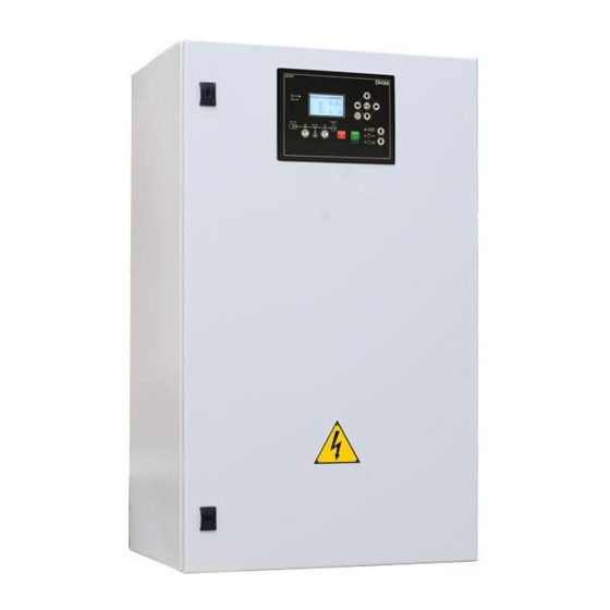
Page 19: Front View
The changeover switch, thanks to its exclusive mechanical structure, can be activated manually by a proper lever. This operation can be useful in case of device failure or in case of connection failure to the remote control logic. Use and Maintenance Manual ATS LOGICA CONTROL PANEL with ATS115... - Page 20 Before supplying, ensure that they have been reconnected correctly according to the diagram. A wrong connection can cause damage to the auxiliary circuits inside the electrical control panel. Use and Maintenance Manual ATS LOGICA CONTROL PANEL with ATS115...
- Page 21 70 Nm WARNING: Before connecting phase and neutral cables of SOURCE A (MAINS), SOURCE B (GENSET) and LOAD to the ATS LOGICA panels, the installer is responsible of checking the type of distribution system of the plant. Pay attention while checking the neutral function. Remember NOT TO SECTION IT if the neutral and protection function has been selected (PEN).
- Page 22 ATS115 controller manages an inverse sequence with respect to the previous one, switching the supply on the Source A (Mains) and deactivating the Source B (Genset) by opening the KB starting contact Use and Maintenance Manual ATS LOGICA CONTROL PANEL with ATS115...
- Page 23 NOTE: with SOURCE A (MAINS) live and with ATS115 on OFF, the motorized changeover switch is commanded to close on SOURCE A (MAINS). Use and Maintenance Manual ATS LOGICA CONTROL PANEL with ATS115...
- Page 24 Interface Power circuit terminal area board Earthing bar Connection Connection Connection power cables- power cables- power cables- XG-Source B XL-LOAD XR-Source A (GENSET) XG-SOURCE (MAINS) (rear) B (GENSET) (front) Use and Maintenance Manual ATS LOGICA CONTROL PANEL with ATS115...
- Page 25 Bars protection screen Earthing bar Connection Connection Connection bars power bars power bars power cables- cables- cables- XG-Source B XL-LOAD XR-Source A (GENSET) XG-SOURCE (MAINS) (rear) B (GENSET) (front) Use and Maintenance Manual ATS LOGICA CONTROL PANEL with ATS115...
- Page 26 Power circuit Connection area bars power cables- XR-Source A (MAINS) (front) Earthing bar REAR Connection Connection bars power bars power cables- cables- XL-LOAD XG-Source B (rear) (GENSET) (rear) Use and Maintenance Manual ATS LOGICA CONTROL PANEL with ATS115...
- Page 27 Power circuit area Connection bars power cables- XR-Source A (MAINS) (front) Connection bars power cables- XG-Source B Earthing bar (GENSET) (rear) Connection bars power cables- XL-LOAD (rear) Use and Maintenance Manual ATS LOGICA CONTROL PANEL with ATS115...
- Page 28 2 types: with contactors (45÷125A), with motorized changeover switch (160÷2500A). The XM auxiliary command is the same for both types. Source Source - Couple of ABB contactors - Use and Maintenance Manual ATS LOGICA CONTROL PANEL with ATS115...
- Page 29 Source A Source B - ABB changeover switch - Use and Maintenance Manual ATS LOGICA CONTROL PANEL with ATS115...
- Page 30 External stop contact (the logic switches on SOURCE A (MAINS)) 4) Possible release of SOURCE B (GENSET), removed by alarm device, on OFF or with SOURCE A (MAINS) live. Use and Maintenance Manual ATS LOGICA CONTROL PANEL with ATS115...
- Page 31 Configuration of the output voltage level 12Vdc 24Vdc (no bridge) Configuration of the battery Configuration of the rapid Configuration of the type of charger as supply charge battery (see manual attached) Use and Maintenance Manual ATS LOGICA CONTROL PANEL with ATS115...
- Page 32 The wire +, currently connected to the terminal XM-L+ by the fuse F1, must be disconnected from the terminal L+ and connected to the + of the diodes bridge D1 as shown in the figure. Use and Maintenance Manual ATS LOGICA CONTROL PANEL with ATS115...
- Page 33 The controller is designed to acquire an input that inhibit the operation in case of lack of sources voltage. Accomplish the option wiring as reported in the diagram adding the terminals 105-106 to the terminal board XM. Configure the parameter: P.0213 = 2501 Use and Maintenance Manual ATS LOGICA CONTROL PANEL with ATS115...
- Page 34 REAR The parameters to configure on the controller are: P.0302 = CT primary current P.0303 = 2 – On Load P.0310 = 5 – CT secondary current Use and Maintenance Manual ATS LOGICA CONTROL PANEL with ATS115...
-
Page 35: Maintenance
Any change made to the panel will be the responsibility of the executor of the change; the executor then becomes the manufacturer. Use and Maintenance Manual ATS LOGICA CONTROL PANEL with ATS115... - Page 36 At the end of its life cycle or in case of demolition, the equipment has to be decommissioned according to the norms in force in the Country of use. It is also required that the identification labels and any other related document are appropriately destroyed. Use and Maintenance Manual ATS LOGICA CONTROL PANEL with ATS115...
- Page 37 Possible problems connected to the ATS LOGICA Panel are listed in the table below. These are general suppositions which are only needed to help explain the problem to the technicians who will then intervene to sort it out. Therefore, the info below has to be considered as general.
- Page 38 In OFF mode the display goes back to the last active page in the moment before the alarm and the visual signalling turns off. Afterwards, set the control card in AUTO position again. Use and Maintenance Manual ATS LOGICA CONTROL PANEL with ATS115...
- Page 39 To shorten the intervention time of SICES Technical Assistance (SAT) please follow the below shown procedure, providing the required data thus allowing an easy problem solving: Try to identify the origin of the fault by consulting the above table; Contact SICES Technical Assistance SAT having the following information at your fingertips: 1) Control Panel data as shown in the plate affixed to the carpentry (**);...
- Page 40 1000 160÷800A 1000 1000 1000 45÷125A 1000 1000 1900 1250 1900 1600 1900 2000 1900 1000 1250÷4000A 2500 1900 1000 3150 1900 1000 1000 4000 1900 1000 1000 160÷800A 45÷125A Use and Maintenance Manual ATS LOGICA CONTROL PANEL with ATS115...
- Page 41 SICES s.r.l. reserves the right to modify this document without prior notice. SICES has made any effort to ensure that the information herein provide are correct; in any case SICES does not assume any liability for the use these information.
Need help?
Do you have a question about the ATS LOGICA and is the answer not in the manual?
Questions and answers