
Related Manuals for Sices ATS115


Summary of Contents for Sices ATS115
- Page 1 File Name: EAAM048102EN.docx Rev. 02 Date: 26/09/2014 ID Document: EAAM030481 Product: ATS115-ATS115Plus User’s Manual...
- Page 2 ....................11 ..................12 ..............12 ..............13 ................. 13 ...................... 14 ..................14 ................20 ..............24 ..................27 Working principle ....................28 ......................28 ........................ 29 ......................30 Special settings ..................... 31 ..................... 31 ....................31 ATS115-ATS115Plus User’s Manual...
- Page 3 In order to know where and how to send these products near you, please contact the proper municipal office. Right recycling and disposal help to preserve nature and to prevent harmful effects to health and environment. ATS115-ATS115Plus User’s Manual 3...
- Page 4 DIF (“Digital Input Function”): the code that follows is used to set the digital inputs. DOF (“Digital Output Function”): the code that follows is used to set the digital outputs. AIF (“Analogue Input Function”): the code that follows is used to set the analogue inputs. ATS115-ATS115Plus User’s Manual...
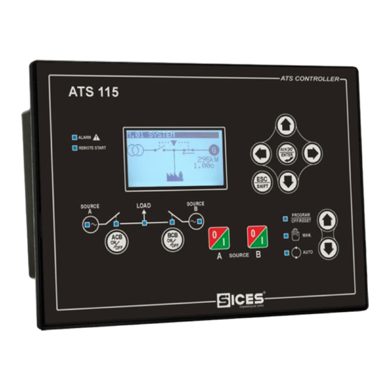
- Page 5 Plus Fig. 1 ATS115-ATS115 Front View Fig. 2 ATS115 Back View ATS115-ATS115Plus User’s Manual 5...
- Page 6 Plus Fig. 3 ATS115 Black View ATS115-ATS115Plus User’s Manual...
- Page 7 Plus ATS115-ATS115 1 – Buttons 2 – Light indicators The controls are made up of 12 buttons (1a, 1b, 1c, 1d, 1e, 1f). In addition, on the front panel there are light indicators (2a, 2b, 2c). ATS115-ATS115Plus User’s Manual 7...
- Page 8 ESC/SHIFT , can adjust the contrast. To reduce the contrast (lighten), press the ESC/SHIFT button together with the LEFT button. To increase the contrast (darken), press the LEFT/RIGHT ESC/SHIFT button together with the RIGHT button. Ref. 1c ATS115-ATS115Plus User’s Manual...
- Page 9 (if the Source B represents the Mains, it has no effects). START / STOP At the controller power-up, pressing it together with the START/STOP A SOURCE B button, it allows to access to special functions. Ref. 1e ATS115-ATS115Plus User’s Manual 9...
- Page 10 It flashes at 50% during the transition between the two previous LIVE statuses. Flashing at 25%, the mains voltage and frequency are on, but below the tolerance range. Ref. 2b Flashing at 75%, the mains voltage and frequency are on, but above the tolerance range. ATS115-ATS115Plus User’s Manual...
- Page 11 (P.0492). Press any button to turn the lamp on again (it is recommended to use the ESC/SHIFT button, which has no function alone). This function can be disabled by setting the parameter P.0492 to 0. ATS115-ATS115Plus User’s Manual 11...
- Page 12 To visualize the pages within the modes, use the buttons LEFT Ref. 1c and RIGHT Ref. 1c. In some modes (e.g.: mode P.xx and mode H.xx), you must press the button ENTER and then the buttons UP Ref. 1c and DOWN Ref. 1c to surf through pages. ATS115-ATS115Plus User’s Manual...
- Page 13 By double clicking ESC/SHIFT, the top status bar is replaced by a System Status message as long as you are on that page. If the message is unavailable, the status bar is not displayed until the button is released. ATS115-ATS115Plus User’s Manual 13...
- Page 14 The first page (000 – Access Code) of the SYSTEM menu requires the setting of the access code if one or more passwords have been assigned (available with the path P.03 PROGRAMMING\ 1.SYSTEM\ 1.1 Security\ 1.1.1 Authentication). ATS115-ATS115Plus User’s Manual...
- Page 15 The “Serial Ports” password can only be set and/or seen through the user panel; when set, this password prevents any command from the serial line. Each parameter of the controller is associated to a user type (see document [1] “SICES EAAM0479xxXA – Parameter Table ATS115” this association is shown in the “ACC” column with a “C”...
- Page 16 “Installer”. So, he/she is able to change the parameters related to the user and to the installer. By entering “ccc” in “P.0000 – Access code”, the operator is identified as “Manufacturer” and allowed to change all parameters. ATS115-ATS115Plus User’s Manual...
- Page 17 The protections management is accessible by means of the 3-PROTECTION menu. As to this, it is important to know that, in order to enable/disable a protection, you just have to change the associated time, leaving the threshold unchanged: by setting the time to zero, ATS115-ATS115Plus User’s Manual 17...
- Page 18 (P.0102) and from the parameter itself (rated power, P.0106). Sometimes, this additional measure can be displayed when the parameter is a percentage of other values, in order to show its absolute value. ATS115-ATS115Plus User’s Manual...
- Page 19 Numerics selected in a number-string couples list (e.g. the type of pressure sensor): as the previous point. Time: as for the numerical parameters, but the controller manages the increase/decrease maintaining valid values (for example, increasing from "00.59", the value goes to "01.00" and not to "00.60"). ATS115-ATS115Plus User’s Manual 19...
- Page 20 In this mode, information on the system status is provided. You can scroll through pages using the LEFT and RIGHT buttons. Page S.01 (STATUS) shows system status information. Part of this information is shown on the top status bar. It contains: Breakers status (ACB closed, ACB and BCB opened, BCB closed etc.). ATS115-ATS115Plus User’s Manual...
- Page 21 The type of connection (direct, via modem, via GSM) and the related status (on standby, communicating etc.). In case of the GSM modem, the information related to the radio signal strength and the provider is shown too. ATS115-ATS115Plus User’s Manual 21...
- Page 22 Note: This page is displayed only if the controller is equipped with the Ethernet optional 192.168.1.112 module. Plus Page S.05 (CONTROLLER) is dedicate to ATS115-ATS115 and contains: The language currently used by the device. It allows you to select among the ones installed.
- Page 23 SHIFT button down, the pages rotation is locked on the one currently displayed. ATS115-ATS115Plus User’s Manual 23...
- Page 24 To the bottom right there is an icon that allows the immediate identification of the fact that the page is related to the MAINS or to the GENSET measures, according to the setting of the parameter P.0100 – “Source A”. ATS115-ATS115Plus User’s Manual...
- Page 25 B and the mains or genset symbol, according to the value set in P.0200 parameter, are displayed. The currents are measured if the primary and secondary CTs values are not set to zero (respectively in the parameter P.0302 – “C.T. Primary Source/Load” and P.0310 – “C.T. Secondary Source/Load”). ATS115-ATS115Plus User’s Manual 25...
- Page 26 Plus If the ATS115-ATS115 has been configured correctly, it is possible to measure the negative-sequence current, the auxiliary current, the neutral current and the differential current. Consequently, they will be displayed on the right side of the screen, identified by the following symbols: ...
- Page 27 The number is displayed in the first line of the multifunctional display, together with the total number of the registrations. Since the log, once reached the maximum recording capacity, overwrites the latest registration, the identification number can change over time. ATS115-ATS115Plus User’s Manual 27...
- Page 28 (with alternator and drive oil mechanic engine) and a control panel that includes: an ACB contactor for Plus the Source A management, a BCB contactor for the Source B management, an ATS115-ATS115 controller for the control of the electric grids and a series of components for the management of the auxiliary parts (relay, fuses, terminals, etc…).
- Page 29 The changeover can be activated by pressing the “ACB” button. The Load will be supplied by the Mains again. The Genset will work until the operator presses the “STOP B” button. ATS115-ATS115Plus User’s Manual 29...
- Page 30 3) The Load is supplied by the Mains with ACB closed. The Genset is not working with BCB opened, ready for a possible new intervention. : The working sequence described above is generic and in some cases INFORMATION may not correspond to the one of your system. For further information, contact the Installer/Manufacturer. ATS115-ATS115Plus User’s Manual...
- Page 31 If the values are between <…>, it means you do not have the rights to access for the parameters change. See the paragraph 4.5.1.1 Access codes to activate the authentication for the “User” password. To go back to the Main menu, press repeatedly the ESC/SHIFT button. ATS115-ATS115Plus User’s Manual 31...
- Page 33 This document is owned by SICES s.r.l.. All rights reserved. SICES s.r.l. reserves the right to modify this document without prior notice. SICES has made any effort to ensure that the information herein provide are correct; in any case SICES does not assume any liability for the use these information.
Need help?
Do you have a question about the ATS115 and is the answer not in the manual?
Questions and answers