Advertisement
Quick Links
Advertisement

Related Manuals for Sices GC600 Series


Summary of Contents for Sices GC600 Series
- Page 1 Mains File name: EAAM055703EN.docx Rev. 03 Date: 14/05/2019 ID Document: EAAM55703 Product: GC600...
- Page 2 User manual 1 Safety information ......................1 2 Maintenance and cleaning ................... 1 3 Information concerning disposal ................1 4 General info........................2 5 Definitions ........................2 6 Main functions ......................3 Front panel ......................3 Buttons (ref. to fig. 1) .................... 4 Indicators (ref.
- Page 3 The manual must always be kept in a safe place where it is readily available for quick reference. The manual should be read carefully, and every paragraph understood by the operators and technicians doing routine and periodic maintenance. If the manual is lost or damaged, ask the installer/manufacturer for a copy, quoting the model, code, serial number and year of manufacture.
- Page 4 Mains The purpose of this manual is to describe boards GC600, GC600 LOCKOUT - is used to indicate a fault that prevents the generator from operating and causes automatic and immediate emergency engine shut-down. POWER-OFF - is used to indicate a fault that prevents the generator from operating and causes the standard automatic engine shutoff (including a cooling phase).
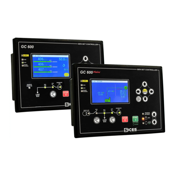
- Page 5 Link 1 - Buttons 2 - Indicators The controls consist of 12 buttons (1a, 1b, 1c, 1d, 1e, 1f). The front panel also has some luminous indicators (2a, 2b, 2c). Mains User manual GC600-GC600...
- Page 6 Pushbuttons Function The genset is disabled; all anomaly signals are disabled. All possible alarms are reset. It is possible to access to the parameter’s configuration. OFF/RESET PROGRAM The Gen-set control module is set for manual gen-set control. Press the START button to start the engine.
- Page 7 Pushbuttons Function In programming mode, it cancels the changes made to a variable value, brings up the previous menu level, or exits programming mode. If it is pressed for at least two seconds in any menu, you exit the programming mode retaining the current menu position for further programming access.
- Page 8 Pushbuttons Function Mains GC600 The button is disabled in the “OFF/RESET”, “AUTO” and “TEST” modes. In “MAN” it is used to open and/or close the Mains contactor to the Load line. To open the Mains switch MCB, with the engine idle, press and hold the “MCB”...
- Page 9 Pushbuttons Function Used to control the stop of the engine in “MAN” mode. The button can be configured in two ways: 1. Stop of the engine in AUTO, TEST or REMOTE START mode with the activation of a lockout. 2. No function. The enabling of the button in AUTO, TEST or REMOTE STOP START is irrelevant.
- Page 10 Signalling Function Flashing at 25% ON signals a COM error (J1939 or MTU): the port is in ERROR-PASSIVE mode. Flashing at 75% ON signals a COM error (J1939 or MTU): the Ref. 2a port is in BUS-OFF mode. Indicates that the CAN-BUS has been disabled or that it is ...
- Page 11 Signalling Function Flashes at 25% ON if open after a closing command. Ref. 2b Flashing at 75% ON if closed after an opening command. Signals BUS line ON. Signals BUS line OFF. Flashing at 50% if the BUS line voltage is outside tolerance range.
- Page 12 As default, the device shows the information on TFT display using a blue background. It is therefore possible to modify this behaviour using parameter P.0499: • P.0499 = 0: blue background (default). • P.0499 = 1: black background. • P.0499 = 2: white background. The messages colour depends on the background colour selected and on the type of information displayed.
-
Page 13: Oil Pressure
In some modes (e.g.: mode P.xx and mode H.xx) to view the pages, the ENTER button, and then the UP Ref. 1c and DOWN Ref. 1cbuttons must be pressed to navigate between pages. If the UP and DOWN buttons have to be used to manage the functions within the mode, the ENTER button must be pressed to activate the said functions, and the Esc/SHIFT button to deactivate them. - Page 14 (1) is temporarily substituted with a status message. Access to the parameters programming mode can be controlled by 3 different PASSWORD levels, which are listed in order of priority. 1. SICES Password 2. Manufacturer Password 3. Installer Password 4.
- Page 15 The INSTALLER can change the User Password and the Installer Password. The MANUFACTURER can display and change all three passwords. As SICES, it is possible to display and change some parameters of plant configuration, related to the parallel functions. Warning: The critical parameters must not be changed by the user.
- Page 16 The variation of the parameters requires the “OFF/RESET” operating mode. Some parameters can also be modified with operating modes different than “OFF/RESET”. If it is not permitted to change a value in any condition, it will be represented in the following manner: <400>...
- Page 17 • The maximum and minimum time of exposition. These times are automatically reset when the PLC program is transferred to the controller or it is possible to force the reset by pressing the buttons ACK/ENTER +Esc/SHIFT for 5 seconds. The page L.02 (PLC LOGIC) contains the information related to the single PLC block. L.02 LOGIC PLC KEY: PLC Block:...
- Page 18 The software codes are currently uploaded on the controller. The necessary internal code to get a temporary SICES level password. The internal temperature of the controller The language currently used by the device. It is also possible to select a different language:...
- Page 19 These values can be those set with the controller parameters or those acquired dynamically by the DHCP server. Page S.06 (SIMONE) is displayed only if the connection with the Sices system “Si.Mo.Ne” is enabled. It shows the controller name (useful to upload it in “Si.Mo.Ne” system and the IP address of “Si.Mo.Ne”...
- Page 20 Esc/SHIFT button pressed, you stop the rotation. If there are no configured inputs on a page, the page is not displayed. On each line the controller shows the configured text for the digital input and the logic status of the input.
- Page 21 Page S.16 (ANALOGUE INPUTS) displays the value of the expansion modules analogue inputs. The page is available only if one or more DITEMP or DIGRIN modules are installed in the system. If more than 8 DITEMP/DIGRIN are used, the controller shows them on two pages, letting them alternate every 2 seconds: (keep Esc/SHIFT pressed to stop the rotation).
- Page 22 In this page it is possible to change the power supplied in the application of parallel with the mains BASE LOAD and IMPORT/EXPORT Page M.02 (MAINS/BARS) displays the main electrical measurements of Mains/Bus. In this page are the voltages, the frequency and the rotation direction of the mains/bars phases. The information really displayed depend on the configuration.
- Page 23 Page M.11 (SYNCHRONIZATION) displays synchronization information. The use of the displayed synchronoscope in MAN mode allows the manual synchronization (par. 6.2.1). Page M.12 (PARALLEL) displays the information when the genset is in parallel with the mains or other gensets. It displays the active and reactive power and the power factor. It also displays currents, medium voltage genset...
- Page 24 In this mode are shown the measures and the statuses which are connected and transit on the CAN- BUS PMCBus, which connects SICES devices among them. All pages of this mode are displayed only if the CAN-BUS PMCBus is enabled.
- Page 25 The current load reserve (the difference between rated power of the gensets and the supplied power) calculated in the hypothesis that the less priority genset is stopped (or that you select a combination of gensets which is lower for rated power). ...
- Page 26 inhibitions to the automatic intervention; the board automatically provides for the closure of the GCB switch (prior opening of MCB if the temporary parallel is not provided with the mains). This mode is priority compared to TEST (that is, it can interrupt the recurring test or replace it).
- Page 27 Following a brief example of the operation sequence of a generic SSB + SSTP system, where, when the LOAD MAINS GENSET ENGINE ELECTRONIC CONTROL DEVICE Mains GC600/ GC600 mains is back, the parallel with the Generator is performed, so not to leave the Loads not supplied. The system consists of a public power line “Mains”, a “Load”...
- Page 28 contactor is opened and the Load stays supplied by the Mains. The genset can be stopped by the “STOP” button. During the synchronisation between Mains and Genset, if necessary, to regulate manually the engine speed and/or the voltage, press ENTER and the buttons LEFT and RIGHT to select speed and voltage...
- Page 29 WARNING! Pressing the "STOP" button during the test activates an alarm which prevents the restart of the engine, which can only be reset in the "OFF RESET" mode. INFORMATION! If a fault occurs on the Mains during the “TEST” phase, causing the automatic activation of the Generator, the operating mode independently passes from “TEST”...
- Page 30 In MAN mode, the engine start/stop and GCB switch are carried out by the operator. By pressing the “GCB” button for the connection of the genset, the synchronisation is activated; GCB is closed, and the load ramp is activated. When supplying, by pressing the GCB button the sequence of power unload is activated and, once over, the GCB is opened.
- Page 31 The calendar/time setting is possible in all operating modes: “OFF/RESET”, “MAN”, “AUTO” or “TEST”. To update the time and/or date of the device, enter the “4.7.1 Date – Time” menu. Use the UP and DOWN buttons to navigate between the sub-menus and the ACK/ENTER button to open the sub-menu.
- Page 32 • 0-MANUAL-OFF (pump off) Press ACK/ENTER to confirm the mode. INFORMATION! The second option (MANUAL-ON) can be disabled by the Gen-set control module in relation to the fuel level (the pump cannot be started with a full tank). Warning: With the fuel pump warning active, the command mode is automatically set to "0-MANUAL- OFF".
- Page 33 All rights reserved. SICES s.r.l. reserves the right to modify this document without prior notice. SICES has made any effort to ensure that the information herein provide are correct; in any case SICES does not assume any liability for the use these information.
Need help?
Do you have a question about the GC600 Series and is the answer not in the manual?
Questions and answers