Advertisement
INSTALLATION
1. Attach the mounting bracket to the desired location on the wall or ceiling, wher-
ever you want to install the camera. Locate a wall stud or a ceiling joist and
secure the mounting bracket using the supplied screws. Please firmly tighten
the screws on the mounting bracket.
2. Connect the one end of the cable to the RCA jack on the rear of the camera
and the other end of the cable to the one of the camera inputs on the rear of
the DVR.
3. Connect the one end of the 4 BNC cable to the Monitor (Video output) on the
rear of the DVR and the other end of the cable to the VIDEO INPUT on the rear
of the monitor.
4. Plug the AC power cord to the monitor and AC outlet.
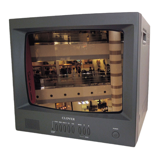
5. Press the POWER button on the front panel of the monitor and then press the
6. Plug the DC plug of AC adapter for DVR (DC 12V 3.5A) to DC jack on the rear
of the DVR and to AC outlet. Turn on the power switch on the rear of the DVR.
Camera
①
60'
POWER
CAM1
CAM2
ON
IN
OUT
1
2
3
4
GND
NO
COM
NC
RX
OUT
OFF
AUDIO
CAM3
CAM4
MON
Yellow
②
2'
Red
Black
Wall
Outlet
4
AC IN
' 4
CDR4060
DVR Rear View
CAUTION
RISK OF ELECTRIC SHOCK
DO NOT OPEN
CAUTION:TO REDUCE THE RISK OF ELECTRONIC SHOCK
DC12V
DO NOT REMOVE COVER(OR BACK)
TX
NO USER SERVICEABLE PARTS INSIDE
REFER SERVICING TO QUALIFIED SERVICE PERSONNEL.
ISO9001
Wall
Outlet
Power
Adapter
C1401
Monitor Rear View
AUDIO INPUT
A
VIDEO INPUT
75Ohm(A)
VCR INPUT
Y/C IN
HI(B)
VCR OUT
VIDEO AUDIO
Wall
Outlet
⑤
A
d
a
t p
r e
B
Advertisement
Table of Contents

Subscribe to Our Youtube Channel
Summary of Contents for Clover CDR-4060
- Page 1 5. Press the POWER button on the front panel of the monitor and then press the VIDEO button. 6. Plug the DC plug of AC adapter for DVR (DC 12V 3.5A) to DC jack on the rear of the DVR and to AC outlet. Turn on the power switch on the rear of the DVR.
- Page 2 Function of Controls at Front ST/BY VIDEO VIDEO HI Y/C R: POWER G: ST/BY Power Button POWER Power is turned On and Off, LED is lit when Power is On. ST/BY Red LED light up when Power is On. Green LED light up when Stand-by is selected. R: POWER G: ST/BY VIDEO Button...


Need help?
Do you have a question about the CDR-4060 and is the answer not in the manual?
Questions and answers