Table of Contents
Advertisement
Quick Links
Advertisement
Table of Contents

Related Manuals for DC Athletics Trail Blazer I

Summary of Contents for DC Athletics Trail Blazer I
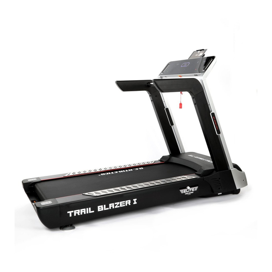
- Page 1 Trail Blazer I MANUAL...
- Page 2 PLEASE READ THE INSTRUCTIONS CAREFULLY BEFORE ASSEMBLY AND USING THE TREADMILL KEEP THE MANUAL FOR FUTURE REFERENCE. WARNING ----When using this treadmill, keep attaching the safety key rope to your clothes. ----When you are running, keep your hands swinging naturally, your eyes staring frontward and never look down at your feet.
-
Page 3: Important Safety Precautions
14. Maximum weight of user 170KGS. 15. Pulse data may not be very accurate, so can not be used for medical purpose. Over-exercise may cause injury, even death. If you have a feeling of dizziness, sickness or other abnormal symptoms, please stop training and consult a doctor immediately. -
Page 4: Assembly Steps
15. Before starting any exercise program, consult with your physician or health professional. He or she can help establish the exercise frequency, intensity (target heart zone) and time appropriate for your particular age and condition. If you have any pain or tightness in your chest, an irregular heartbeat, shortness of breath, feel faint or have any discomfort while you exercise, STOP! Consult your physician before continuing. - Page 5 STEP 3: 1. Link the left end cover backlight power lower wire (71) with left end cover backlight power upper wire (72), 2. Link the right end cover backlight power lower wire (73) with right end cover backlight power upper wire (74), 3.
- Page 6 STEP 4: 1. Link the connecting wire A on the front armrest (6) to the B point of the heart rate lower wire (78) 2. Insert the armrest (8L/R) to the front armrest (6) separately, match the holes, then lock them tightly with hex bolt (58) and locked washer (70).
- Page 7 STEP 5: 1. Please connect below wires as Image 1 shown: Connect heart rate connecting wire (79) with heart rate upper wire (80); Connect computer connecting wire (82) with computer upper wire (83). 2. Lock the computer frame (7) to the rear upright tube (4L/R) with hex bolt (58) and locked washer (70), then cover the rear upright tube plug (28).
- Page 8 image 1: STEP 6: 1. Tighten the Motor side cover (22L/R) to the main frame (1) with cross slotted washer screw (57) ; 2. Put the motor cover (18) to the main frame (1), match the holes, then lock the motor cover (18) to the main frame (1) with cross slotted washer screw (56) and cross slotted washer screw (57).
- Page 9 STEP 7: Insert the end of power cord (86) to the power plug of the main frame (1). The method of using the Shelf: Part Description - 8 -...
- Page 10 Image 4 Board Extended frame Image 1 Supported frame PAD/Phone Step one: Hold the boss of the board A, pull the extended frame B and supported frame C out from the computer. (the position of the boss is showed as picture 4) Image 2 Step two:...
-
Page 11: Grounding Methods
Supported frame PAD/Phone Step one: Pull out the board A as the direction of the arrow in the picture, take away the PAD/Phone. Step two: Push the board A to the right, then rotate it as the direction of the arrow in the picture. Step three: Hold the board A, let the extended frame B and supported frame C turn back in the computer. -
Page 12: Technical Parameter
This product is equipped with a cord having an equipment-grounding conductor and agrounding plug. The plug must be plugged into an appropriate outlet that is properly installed and grounded in accordance with all local codes and ordinances. DANGER – Improper connection of the equipment-grounding conductor can result in a risk of electric shock. -
Page 13: Window Display
1. Window display 1.1. : display incline and calories in turn : display incline : display calories 1.2 : display time 1.3. : display distance and steps in turn .: display distance : display steps 1.4. : display speed and heart rate in turn : display speed : display heart rate 1.5.Middle dot matrix: display the runway and the number of turns, 400... - Page 14 used to set the correlation, you can press to start the treadmill after finishing setting. 2.3. Start key “START” for startup, press SRATR the treadmill will run at minimal speed 2.4. Stop key “STOP” for stop, the treadmill will stop when the key pressed. 、...
-
Page 15: Manual Mode
4. Operations during the exercise: 4.1. Press key to reduce the speed of the treadmill. 4.2. Press key to increase the speed of the treadmill. 4.3. Press key to reduce the incline of the treadmill. 4.4. Press key to increase the incline of the treadmill. 4.5. - Page 16 Setup time /20 = Each segment of the running time 10 11 12 13 14 15 16 17 18 19 20 SPEED INCLINE 1 SPEED INCLINE 1 SPEED INCLINE 1 SPEED INCLINE 2 SPEED INCLINE 3 SPEED INCLINE 3 SPEED INCLINE 4 SPEED INCLINE 4...
-
Page 17: User Programs
8. User programs: In addition to 18 built-in programs, the treadmill also has 3 customized programs to support the customized setting based on the user’s specific situation: U01, U02 and U03. 8.1. Settings of user programs: In the standby mode, press key in succession to the user programs(U01-U03),and 、... - Page 18 10. Range of values: Set parameter Initial value Set initial value Setting range Display range Time(minute:second) 0:00 30:00 5:00-99:00 0:00-99:59 Incline(level) 0-15 1.0-22.0KMH Speed(KM/H) 0.6-13.6MPH Distance(KM) 0.00 1.00 0.50-99.9 0.00-99.9 Heart rate(Times/min) 50-200 Calories(Kilocalorie) 50.0 10.0-999.0 0.0-999.0 11. Functions of the safety key: In any state, pulling off the safety key can stop the treadmill urgently, when the treadmill stops urgently, the window displays "---", and the buzzer sends a "BB"...
-
Page 19: Power Off
52 101 53 100 54 100 154 80 1.Start at the 0 incline section, also with the lowest speed 2.The first minute is the warm up exercise and can adjust the speed and incline manually 3.After the warm up, calculate the heart rate D value (target heart rate- the user’s heart rate) for the following process: A.(Target heart rate- the user’s heart rate) >0, when the speed increase 0.5KM/H and reach to the tip speed, the incline will increase 1 level accordingly. - Page 20 16. Attentions: 15.1 Check whether the power supply is loaded before exercising; Check whether the safety key does work. 15.2 During the exercise, you can pull out the safety key in the abnormal situation, the treadmill will quickly slow down to stop. Then insert the safety lock, reset the device, and wait to input instructions.
-
Page 21: Exercise Instructions
18.Calorie calculation method: 70.3×V(Km/h)×t(h)×(1+?%) When the lifting is 0, the calorie consumption for each 1km of running is about 70.3cal. EXERCISE INSTRUCTIONS 1. The Warm Up Phase This stage helps get the blood flowing around the body and the muscles working properly. It will also reduce the risk of cramp and muscle injury. -
Page 22: Maintenance Instructions
As you get fitter you may need to train longer and harder. It is advisable to train at least three times a week, and if possible space your workouts evenly throughout the week. To tone muscle while on your Treadmill you will need to have the resistance set quite high. This will put more strain on our leg muscles and may mean you cannot train for as long as you would like. -
Page 23: Tensioning The Belt
Picture A:If the belt has drifted to the RIGHT Picture B: If the belt has drifted to the LEFT TENSIONING THE BELT If you can feel a slipping sensation when running on the treadmill, the running belt must be tightened. In most cases, the belt has stretched from use, causing the belt to slip. -
Page 24: Walking Belt And Deck Lubrication
WALKING BELT AND DECK LUBRICATION This treadmill is equipped with a pre-lubricated, low maintenance deck system. The belt/ deck friction may play a major role in the function and life of your treadmill, thus requiring periodic lubrication. We recommend a periodic inspection of the deck. We recommend lubrication of the deck according to the following timetable: ➢... - Page 25 EXPLODED DRAWING - 24 -...
-
Page 26: Parts List
PARTS LIST Part Part Description Description Hex bolt M10*115 Main frame Hex bolt M10*75 2 L/R Upright tube 1 p.r. Linking metal plate Hex bolt M12*50 4 L/R Rear upright tube 1 p.r. Cross pan head screw M6*20 Incline frame Cross pan head screw M6*15 Front armrest Cross slotted washer screw M5*15... - Page 27 Cushion Overload protector Protective plug Power plug Square end cap Motor front cover Cap 1 cross countersunk head screw M3*15 Cap 2 Hex nut M3 Pressing board Water bottle holder Hex bolt M10*70 Amplifier board (Optional) Hex bolt M10*40 Filter (Optional) Hex bolt M10*20 Inductor (Optional ) Hex bolt M10*40...
Need help?
Do you have a question about the Trail Blazer I and is the answer not in the manual?
Questions and answers