Advertisement
Quick Links
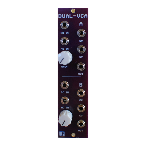
Dual VCA v1.2 – Assembly Guide
Thank you for purchasing this module! This is a reasonably simple build with a small number of
components.
The module is designed and sized for Eurorack systems. You will need a 16-10 pin eurorack power
ribbon connector with –12/0/+12 which is connected to a synth power supply.
Follow the parts lists, these instructions and the PCB silkscreen text to build the module.
The module consists of 1 PCB board and a front panel.
There are components installed on BOTH sides of the boards. Please ensure that you place the
components on the correct side. When referring to the TOP of a board we mean the side with the
pmF logo. The BOTTOM has no logo.
You may need to clean up the board edges with wire cutters and/or a file to remove the remains of
the tabs from the fabrication process. This is particularly important for the edges containing the
jacks. These edges will need to mate flush with the front panel.
You must follow the order of assembly as described below since some components will be soldered
underneath other components.
Constructing the board
1. Clean board edges with wire cutters and/or file to remove the manufacturing tabs.
Page 1 of 10
Advertisement

Related Manuals for PMFoundations Dual VCA


Summary of Contents for PMFoundations Dual VCA
- Page 1 Dual VCA v1.2 – Assembly Guide Thank you for purchasing this module! This is a reasonably simple build with a small number of components. The module is designed and sized for Eurorack systems. You will need a 16-10 pin eurorack power ribbon connector with –12/0/+12 which is connected to a synth power supply.
- Page 2 2. Range adjustment resistors Using the included R10/R26 (75k) resistors, the VCA shuts off when the initial gain panel control is just above 0. If you prefer a VCA which shuts off completely at just below the mid point of the panel control, install wire links in place of R10 and R26.
- Page 3 5. IC Sockets Install the sockets on the TOP of the board. Observe the notch or mark on the sockets and align with the notch or mark on the board. Solder. Page 3 of 10...
- Page 4 6. Power socket Install the 10 pin power socket on the TOP of the board. The opening in the right angle socket should face OUT from the board as shown in the photo. Solder. 7. Ceramic/film Install the ceramic/film capacitors on the TOP of the board. Solder and clip the leads. 8.
- Page 5 9. Transistors Install the transistors on the TOP of the board. These are polarized components. Align the outline with the outline on the board. Solder and clip the leads. Page 5 of 10...
- Page 6 10. Trimmer resistors Now populate the trimmer pots on the TOP of the PCB. Make sure they are oriented so that the screw is above the circle on the silk screen. 11. Potentiometers If the pots have positioning lugs on the front, cut these off with a sharp pair of flush cutting pliers.
- Page 7 Page 7 of 10...
- Page 8 12. 3.5mm Jack Sockets Install SOME jacks on the top and SOME on the BOTTOM. Tack one pin only with solder. These will be finalized later. Please ensure they are on the CORRECT SIDE OF THE BOARD. See Photo. 13. Alignment 1.
- Page 9 5. Remove the front panel and solder all the remaining pins on the jacks and pots. 14. Do not install the ICs until the voltage tests are complete. 15. If you do not trust all your soldering and connections, carry out the voltage tests below before installing the ICs Page 9 of 10...
-
Page 10: Voltage Tests
Voltage tests 1. You do not have to do these tests if you are completely happy with your soldering and are sure there are no bridges or incorrectly placed components. However, these tests will ensure that the correct power supplies are sent to the IC pins to ensure they will not be damaged on power 2.
Need help?
Do you have a question about the Dual VCA and is the answer not in the manual?
Questions and answers