Advertisement
Quick Links
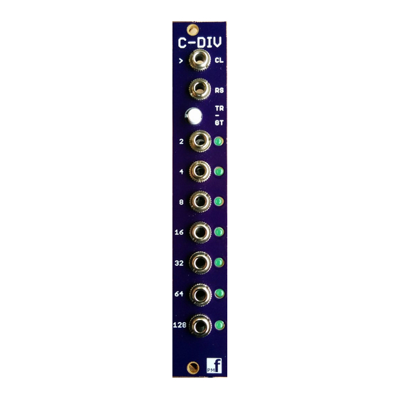
Clock Divider v1.0a – Assembly Guide
Thank you for purchasing this module! This is an average build with some precision integrated
circuits. Some of the pads are quite small and you will need a chisel tip or screwdriver tip soldering
iron and the skill to solder these tiny joints.
The module is designed and sized for Eurorack systems. You will need a 16-10 pin eurorack power
ribbon connector with –12/0/+12 which is connected to a synth power supply.
Follow the parts lists, these instructions and the PCB silkscreen text to build the module.
The module consists of 1 PCB board and a front panel.
You must follow the order of assembly as described below since some components will be soldered
underneath other components.
NOTE: Build options
Page 1 of 12
Advertisement

Summary of Contents for PMFoundations Clock Divider
- Page 1 Clock Divider v1.0a – Assembly Guide Thank you for purchasing this module! This is an average build with some precision integrated circuits. Some of the pads are quite small and you will need a chisel tip or screwdriver tip soldering iron and the skill to solder these tiny joints.
- Page 2 Pulse level: R5, 6, 12, 13, 18, 19, 22, 23, 25, 26, 28, 29, 32, 33 set the clock output pulse voltage level. The following options are suggested: • STANDARD BUILD: 5V pulse: R5,12,18,22,25,28,32 = 1.8K; R6,13,19,23,26,29,33 = 1.5k • 10V pulse: R5,12,18,22,25,28,32 = 1.2K;...
- Page 3 Constructing the board 1. Resistors See above for options. Install the flat resistors on the TOP of the board. Solder and clip the leads. 2. Diodes Page 3 of 12...
- Page 4 Install the diodes on the TOP of the board. These are polarized components. Align the stripe on the diode with the stripe marked on the board. Solder and clip the leads. Page 4 of 12...
- Page 5 3. IC Sockets Now Install the sockets on the TOP of the board. Observe the notch or mark on the sockets and align with the notch or mark on the board. Solder. 4. Power socket Install the 10 pin power socket on the TOP of the board. This must be installed with the correct orientation or the module will be damaged when the power is connected.
- Page 6 6 pin jumper (JP1) See above for options. For standard operation: Put wire links from A2-A3 and from B2-B3. 6. Ceramic/film/polypropylene capacitors Install the ceramic/film capacitors on the TOP of the board. Solder and clip the leads. 7. Transistors Install the transistors on the TOP of the board. These are polarized components. Align the outline with the outline on the board.
- Page 7 8. Electrolytic capacitors Install these on the TOP. Make sure you orient these capacitors correctly. The longer lead and/or the lead marked with a + needs to be inserted into the hole that has the “+” marking near it. Leads marked with “-“ go in the board hole WITHOUT the “+”. Solder and clip the leads. 9.
- Page 8 11. Alignment 1. Place the front panel over the board so that the 3.5mm jacks align with the holes in the panel. 2. Put nuts on the jacks and FULLY TIGTEN all of them. Do not overtighten! 3. Now fully solder as many pins as you can reach of each jack and switch. 4.
-
Page 9: Voltage Tests
Place the panel over the jacks and pots and position the LED in the holes. Place the short lead into the pad with the flatted edge of the silk screen next to it. Solder and clip the leads. 13. If you do not trust all your soldering and connections, carry out the voltage tests below before installing the remaining ICs Voltage tests 1. -
Page 10: Final Assembly
g. At IC3 pin 7= 0V h. At IC4 pin 14 approx = +12V At IC4 pin 7= 0V At IC5 pin 14 approx = +12V k. At IC5 pin 7= 0V At IC6 pin 14 approx = +12V m. At IC6 pin 7, 12, 13= 0V n. - Page 11 Page 11 of 12...
- Page 12 Page 12 of 12...


Need help?
Do you have a question about the Clock Divider and is the answer not in the manual?
Questions and answers