
Related Manuals for ARTHUR HOLM ERT 30


Summary of Contents for ARTHUR HOLM ERT 30
- Page 1 User Guide ERT 30 / ERT 60 IP to RS422 interface control Technology Serving Desing Danish craftmanship Mediterranean soul...
-
Page 3: Table Of Contents
TABLE OF CONTENTS EC REGULATIONS AND SECURITY SAFETY INSTRUCTIONS SYSTEM DESCRIPTION CONTROLS AND CONNECTORS SYSTEM CONFIGURATION AHLINK AHNET ADDRESS CONFIGURATION AHNET PROTOCOL INFORMATION ON DISPOSAL WARRANTY TERMS AND CONDITIONS... - Page 4 WELCOME Thank you for purchasing an ARTHUR HOLM product. Our product range has been designed for a seamless integration and for a maximum reliability. Please, read this installation and operating instructions carefully and keep them in a safe place for future reference.
- Page 5 ABOUT US The Company Arthur Holm has its origins in the Danish furniture designer Jorgen Alex Jensen, who was active during the sixties and the seventies. His design inspiration and his concept of ergonomics have been continued by his family, who is the design force behind Arthur Holm product range. The...
-
Page 6: Ec Regulations And Security
EC REGULATIONS AND SECURITY ATTENTION: Do not disassemble or modify the device in any way. This symbol warns of the presence of dangerous un-insulated voltages inside some of the components, of sufficient magnitude to expose people to risk of electronic shock. This symbol draws attention to important use and maintenance instructions in the guide that accompanies the unit. - Page 7 SAFETY INSTRUCTIONS Wiring connected to hazardous voltage requires installation by qualified personnel or the use of ready-made flexible cables. For your security, your equipment must be connected to an electrical outlet with grounding connection protection. Since the plug is used to disconnect the device, the operating electrical outlet must be in an easily accessible place.
- Page 8 SAFETY INSTRUCTIONS to radio or television reception, which can be determined by turning the equipment off and on, the user is encouraged to try to correct the interference by one or more of the following measures: ∙ Reorient or relocate the receiving antenna. ∙...
-
Page 9: System Description
The ERT is an Ethernet IP to RS422 interface, that allows the user to use the local network to send AHnet commands to the Arthur Holm or Albiral motorised devices. By opening an IP ERT port, the system can send the AHnet commands using a local network and the ERT will send the commands to both RS422 RJ45 buses. -
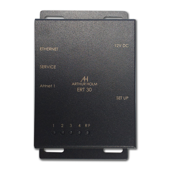
Page 10: Controls And Connectors
CONTROLS AND CONNECTORS 12V.D.C.: Power input connector. Plug the power supply supplied with the unit. Set-up: Eight deep switches to control and setup the unit: - DIP1: Activates the radio signal to control the unit using AHlink app. - DIP2: Activates the automatic AHnet ID configuration on the RS422 bus. - Page 11 USB connector used only for firmware upgrades. AHnet1: RJ45 RS422 port. To control the units using AHnet commands, connect the Arthur Holm or the Albiral units on this connector. AHnet2: RJ45 RS422 port. To control the units using AHnet commands, connect the Arthur Holm or the Albiral units on this connector.
- Page 12 CONTROLS AND CONNECTORS LEDs system indicators LED1: Change the state when a AHnet command is received from the two RS422 ports (AHnet1 or AHnet2). LED2: Change the state when the unit receives data from the local network port (ETHERNET). LED3: Not used.
-
Page 13: System Configuration
RS422 ERT ports (AHnet1 and AHnet2). The Arthur Holm or the Albiral devices have a AHnet IN and a AHnet OUT port to easily install a RS422 BUS. The next picture shows a... -
Page 14: Ahlink
AHLINK To control and set-up the unit using the AHlink app, download the AHlink from the App Store (IOS system) or from Google Play (Android system). The app is free. Execute the AHlink on your mobile phone. On the AHlink app options, it is recommended to not select Auto Connect and select Portrait on Orientation. - Page 15 AHLINK When selecting the device, the first page will upload on the mobile phone. When the mobile app is connected to the unit, the RF LED lights up.
- Page 16 AHLINK The first line shows the model name of the device. SERIAL Serial number of the unit. Firmware version. ADDRESS Set-up the AHnet address to send a command. Use address 0 to broadcast the command instruction. DYNAMIC2 CONTROL Sends basic commands to Dynamic2 monitors family.
- Page 17 AHLINK NETWORK CONFIGURATION Change the network configuration and press the “NETWORK INI” button to update the new network settings.
-
Page 18: Ahnet Address Configuration
AHNET ADDRESS CONFIGURATION There is an ERT functionality that helps users set-up the AHnet address. To send AHnet commands to a unit, the user needs to set-up the AHnet address to individually send the commands. When installing the unit (monitor, microphone or other device) the user should set-up a different AHnet address on each unit. - Page 19 AHNET ADDRESS CONFIGURATION...
-
Page 20: Ahnet Protocol
AHNET PROTOCOL AHnet protocol Using 5 bytes communication: BYTE 0 START BYTE BYTE 1 ADDRESS BYTE BYTE 2 COMMAND BYTE BYTE 3 VALUE 1 BYTE 4 VALUE 2 BYTE 0 is the header and should always FA in HEX mode. BYTE 1 is the AHnet address unit to send the command. - Page 21 AHNET PROTOCOL Dynamic2 family COMMAND DESCRIPTION RESPONSE FA XX 01 01 00 GO UP FB XX 01 01 00 FA XX 01 00 00 GO DOWN FB XX 01 00 00 FA XX 02 01 00 SCREEN ON FB XX 02 01 00 FA XX 02 00 00 SCREEN OFF FB XX 02 00 00...
- Page 22 AHNET PROTOCOL Dynamic3 family COMMAND DESCRIPTION RESPONSE FA XX 01 01 00 GO UP FB XX 01 01 00 FA XX 01 00 00 GO DOWN CLOSED FB XX 01 00 00 FA XX 01 02 00 GO DOWN SCREEN UP FB XX 01 02 00 FA XX 02 01 00 SCREEN ON...
-
Page 23: Information On Disposal
INFORMATION ON DISPOSAL FOR USERS OF WASTE ELECTRICAL & ELECTRONIC EQUIPMENT This symbol on the products and/or accompanying documents means that used electrical and electronic products should not be mixed with general household waste. For proper treatment, recovery and recycling, please take these products to the designated collection points, where they will be accepted on a free of charge basis. -
Page 24: Warranty Terms And Conditions
WARRANTY TERMS AND CONDITIONS Albiral Display Solutions warrants this product against manufacturing defects and workmanship for a period of two (2) years from the date of purchase, subject to the conditions below. 1. Electrical, electronic boards, accessories and power supply are warranted against manufacturing defects and workmanship for a period of two (2) years from the date of purchase. - Page 25 If you have any doubts concerning the terms of this warranty, please contact: business@albiral.com +34 938 502 376 Copyright © Dec. 2019. All rights reserved Albiral Display Solutions SL. Registered trademarks: Albiral, Arthur Holm, Pixtron Broadcast...
- Page 26 Patents P27178ITEP P27178RUPC MU17180ES00 P27178USPC MU17301ES00 P27284DEEP MU17322ES00 P27284EPPC MU17413ES00 P27284ESEP MU17445ES00 P27284GBEP MU17854ES00 P27284RUPC MU17868DEPC P27284USPC MU17868RUPC P27715ESEP P24821DEEP P28089DEEP P24821ESEP P28089ESEP P24821GBEP Fàtima 25, Sant Hipòlit de Voltregà P28089ITEP P24821USPC 08512 Barcelona – Spain P28089USPC P27178DEEP tel: +34 93 850 23 76 / 23 83 P28090EP00 P27178EPDV01 fax: +34 93 850 25 50 / 23 72...
Need help?
Do you have a question about the ERT 30 and is the answer not in the manual?
Questions and answers