
Related Manuals for Condair AX


Summary of Contents for Condair AX
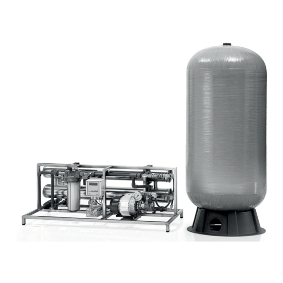
- Page 1 CONDAIR AX Reverse osmosis system INSTALLATION AND OPER- ATING MANUAL Condair AX reverse osmosis system 01/01/2021 Air humidification, dehumidification and evaporative cooling...
- Page 2 Non-compliance with this is punishable by law and will result in compensation for damages. Liability Condair GmbH does not accept any liability due to incorrect installation or operation of the equipment or due to use of parts/components/equipment that are not authorised by Condair AG. Copyright notice...
-
Page 3: Table Of Contents
Contents General safety instructions Explanations of symbols and instructions Operator obligations Personnel obligations Training of personnel Intended use Hazards when handling the equipment Protective devices and safety measures to avert hazards 1.7.1 Protective devices 1.7.2 Informational safety measures Safety instructions for maintenance work Disposal of system parts and operating materials 1.10 Unauthorised modification and replacement parts... - Page 4 Operations log for reverse osmosis systems Maintenance 9.3.1 Maintenance plan for reverse osmosis systems Appendix 10.1 Assembly layout (schematic) 10.2 P&I diagram 10.3 Dimensions of AX 02 10.4 Dimensions of AX 05, 12 and 20 10.5 Dimensions of AX 30 and 50 Contents...
-
Page 5: General Safety Instructions
General safety instructions Explanations of symbols and instructions This operating manual contains important information on the safe operation of the system. This operating manual, in particular the chapter “Safety instructions” must be observed by all persons working on the system. This applies to the installation company as well as to the system operator. -
Page 6: Personnel Obligations
Personnel obligations All persons who are commissioned to work on the system or who carry out such work inde- pendently undertake the following before commencing work: T o read the chapter on safety and the warnings in this operating manual and to acknowl- edge with their signature that they have understood them. -
Page 7: Protective Devices And Safety Measures To Avert Hazards
C heck the electrical equipment of the installation regularly. Remove loose connections and scorched cables immediately. T he switch cabinet must be kept locked at all times. Access is only allowed to authorised person- nel. I f work on live parts is required, a second person must be called in who can switch off the main switch if necessary. -
Page 8: Safety Instructions For Maintenance Work
Safety instructions for maintenance work T he operator must ensure that all maintenance, inspection, and assembly work is carried out by authorised, qualified technicians who have sufficiently informed themselves by studying the operating manual in detail. B efore carrying out any repair or maintenance work, the system must be switched off and secured against being accidentally put into operation. The procedures for shutting down the system described in section “Commissioning and decommissioning”... -
Page 9: Safety Instructions For Storage
1.12 Safety instructions for storage CAUTION! The reverse osmosis system is protected by a preservative against microbial contamination and against risk of frost down to -10°C. At room temperature (< 25°C), this preservative must be purged and replaced within 6 months at the latest. At higher temperatures, the protection period is correspondingly shorter (3 months at 30°C). -
Page 10: Principles Of Reverse Osmosis Systems
Principles of reverse osmosis systems Calculation equations The permeate output, the concentrate output and the permeate conductivity are determined by read- ing the corresponding measuring equipment on the system. If no indicating instruments (e.g. variable area flow meter) are present, the permeate output and the concentrate output are determined by manual volumetric measurement. Feed water output permeate output + concentrate output (permeate output [l/h]) Yield [%]... -
Page 11: Conductivity Of First Permeate
CAUTION! If the system is operated at a feed water temperature higher than the design temperature, the maxi- mum permeate output specified on the nameplate and in the technical data must not be exceeded! Temperature T in °C Information Correction factor 1.30 1.28 1.25 If the actual permeate output 1.21 exceeds the maximum permissi- 1.18 ble permeate output, it must be 1.15 reduced by lowering the working... -
Page 12: Transport And Storage
Transport and storage Transport to the customer CAUTION! During transport, all units must be secured against slipping and falling over! Tipping from a fixed position is not permitted! If parts of the equipment protrude from the base area of the pallet, then such protruding parts must not be damaged when further parts/equipment are loaded. T he transport weight corresponds to the tare weight and can be found in the technical data. H owever, the system may be damaged by extreme frost. The units are filled with a preservative/ antifreeze mixture prior to delivery. -
Page 13: Technical Data / Product Description
Technical data / Product description Technical data Type AX Recommended quality of the feed Soft water 0˚dH water Ratings 1) Permeate output at 3 bar Permeate output at 1 bar Yield when taking in - Soft water - Hard water 35–40 Desalination rate 96 / 98 Intake pressure (min./max.) -
Page 14: Application Limits
Application limits The membranes are wear parts in the longer term. Their service life depends on the feed water qual- ity and the operating conditions. In order to achieve a projected membrane service life of 3 years, the reverse osmosis systems should be operated with softened water or with hard water according to the system type, in each case in the same quality as drinking water according to the German Drinking Water Ordinance and according to the following additional specification: Parameter... -
Page 15: Product Description
Product description 4.3.1 Layout The following P&I diagram shows the structure of an AX reverse osmosis system: Supply limit Feed Permeate water F-01 P-01 M-01 Supply limit D-01 Supply limit MSR point list Actuators Local display of pump pressure and... -
Page 16: Function
4.3.2 Function The RO feed water reaches the HP pump via a residual hardness monitor (optional accessory, only when using softened water) and a protective cartridge filter (grade of filtration 5 µm). This pump con- veys the water at high pressure (level depends on the size of the system and the desired permeate pressure) through the semi-permeable membranes. Water largely freed from salts passes through the membranes and forms the permeate (desired product). -
Page 17: Installation And Assembly
Installation and assembly Installation 5.1.1 Requirements of the installation site T he space required for the unit is derived from the dimensions specified in the technical data. In addition, there should be 0.8 m of space in front of the unit to allow access for operation and 1.0 m of space to the side for maintenance. T he place of installation must comply with the ambient conditions as specified in the technical data. -
Page 18: Water Connections
Water connections 5.2.1 Required qualification of assembly personnel NOTE The water connection must only be carried out by trained specialist personnel. General directives (DIN, DVGW, SVGW, ÖKGW) and local installation regulations must be observed when installing the system. 5.2.2 Establishing the water connections Feed water Remove the sealing disk from the screw connector in the feed water inlet and keep it. -
Page 19: Electrical Connection
Electrical connection 5.2.1 Required qualification of assembly personnel DANGER! The electrical installation must be carried out by an electrician in compliance with the installation guidelines of the VDE, utility suppliers, factory standards, etc. according to the valid country-specific regulations. 5.3.2 Establishing the electrical connections DANGER! Before connecting the system to the power supply, make sure that the corresponding on-site main switch is switched off. -
Page 20: Terminal Connection Table
5.3.5 Terminal connection table Name Allocation Specification Terminals in front of the relays, lower edge of the circuit board: 5 mm grid, for solid / finely stranded conductors up to 1.5 mm² Supply, feed Supply 230V, 50...60Hz, 6,3 AT (Power IN) Normally open relay Main output High-pressure pump output, wet, via 6.3 AT (Main Out1) fuse L (NO contact) Normally open relay Universal output 2 Inlet valve... -
Page 21: Commissioning And Decommissioning
Commissioning and decommissioning Commissioning 6.1.1 Qualification of commissioning personnel CAUTION! The system must be commissioned by qualified specialist personnel. NOTE Before commissioning the system, all screw connections must be tightened. 6.1.2 Flushing out the preservative WARNING! The preservative solution contains 1.5% sodium bisulphite and 20% glycerine. The flushed-out pre- servative solution must be discharged into the sewage system in accordance with the locally applica- ble discharge regulations. -
Page 22: Configuring Permeate Outlet Pressure
PS 2. The factory setting is 3 bar. If a lower outlet pressure is desired, the charging pressure in the membrane pressure vessel must also be adjusted by increasing or releasing pressure according to the following table: Permeate outlet pressure at which production Charging pressure in the membrane pressure is switched off in bar vessel... -
Page 23: Control Panel
Control panel Control and display elements LED Rot Display LED Grün ENTER Tastatur The keyboard includes the following four keys: P ress the M key to enter the user menu and the main menu or to exit the main menu. This navigates to the next menu item in the user menu. -
Page 24: User Menu
User menu 7.2.1 Structure and content The default value for the user password is 1111. It can be changed by the user in the menu below. User password Display of the operating time of the system that has elapsed. Cannot be changed! To skip, press the M key! Operating hour 000004 h... - Page 25 Lower limit of conductivity for a warning Lower limit(W) 9002.0 μS/cm Upper limit of conductivity for a warning Upper limit(W) 0023.0 μS/cm Upper limit of conductivity for an alarm Upper limit(A) 00250 μS/cm S ystem response to a conductivity alarm. You can select “Switch off” and “Do not switch off”. Select “Switch off” only if enough permeate is pre-produced that will suffice until a technician arrives. Response Syst. conductivity do not switch off Lower limit of temperature for an alarm Lower limit(A) 02.0...
-
Page 26: Entries/Changes In The User Menu
Press M key to select “No” scrolling display is shown Press ENTER to select “Yes” Technician menu, password request (only for technicians) Expanded ? ENTER ENTER 7.2.2 Entries/changes in the user menu I n the user menu (see Appendix), you can change user-specific parameters that allow you to adapt the system function to the conditions in the environment. Press the M key, you will be prompted to enter the password (the default password is 1111): User password... -
Page 27: Scrolling Display
Press ENTER again to save the value of “Retry time” and at the same time jump to the next parameter, the lower limit for the alarm value LF (conductivity). In the same way, skip or change further parameters until the prompt “Expanded? No/Yes” appears, to which you answer “No” by pressing the M key. Lower limit(A) 0001.0 μS/cm NOTE It is not possible to return to previous items in the user menu. -
Page 28: Interrupted Operating Sequence
Production OFF Pause flush i ndicates that after a longer production pause — the default is 24 h — a forced flushing takes place, during which the HP pump is switched off Production ON Pause flush i ndicates that after a longer production pause — the default is 24 h — a forced flushing takes place, during which the HP pump is switched on NOTE “Production ON” indicates that the HP pump is running and permeate is being produced. “Production OFF” indicates that the HP pump is idle and no permeate is being produced. 7.3.2 Interrupted operating sequence Current alarms, messages and information are displayed, can be selected and acknowledged on a... - Page 29 alarm by pressing ENTER. Forced stop Press the key again to acknowledge the alarm. Press the M button to exit the “Alarms” sub-menu. Acknowledge Forced stop NOTE Alarm acknowledgement if the cause of the alarm persists If an alarm is acknowledged but its cause has not been eliminated, the alarm appears again when the delay time assigned to the cause of the alarm has elapsed.
-
Page 30: Parameters
Parameters I n order to ensure a meaningful control sequence, the control parameters must be correctly config- ured at the time of delivery from the factory. During commissioning, the technician can use the fol- lowing table to check whether the settings are correct and, if necessary, correct them or adjust them to the local situation. Con- Main Menu tree —... - Page 31 Main Configured Menu tree — parameters Area Default value menu value With overflow / Without over- Design without over- flow flow Normally Normally Contact closed / nor- closed mally open Tank module Message re- None / display / None Tank level sponse why / alarm System re- Do not switch...
-
Page 32: Fault Elimination
Fault elimination General information By using high-quality individual components and due to the built-in safety and monitoring devices, a very high degree of operational reliability is achieved. S hould a malfunction nevertheless occur, the fault can be easily identified and the cause eliminated using the fault table set out below. If serious malfunctions occur, please contact the manufacturer (see nameplate). WARNING! Fault elimination may only be carried out by qualified and instructed personnel in compliance with the safety regulations in chapter A of this operating manual! - Page 33 Fault/message Possible causes Remedy Display unlit Mains supply interrupted Establish mains supply 230VAC/6.3 AT fuse defec- Replace fuse concerned tive Controller defective Replace controller Forced stop display ON Residual hardness sensor Check soft water quality triggered (if present) Check sensor and replace it, if required Display shows “Low inlet Feed water pressure too low...
-
Page 34: Flushing The Concentrate
W hen flushing the concentrate, the concentrate side of the membrane(s) is flushed at a higher speed due to the increase in the concentrate volume flow and, due to the associated increase in shear forces, easily detachable deposits are removed and flushed out. Flushing the concentrate should last at least 60 minutes and should be carried out as follows: Log the actual values (enter in operations log according to chapter H) Open the concentrate control valve completely or remove the concentrate screen (depending on the type of system). -
Page 35: Inspection And Maintenance
Inspection and maintenance Inspection and maintenance work 9.1.1 Safety instructions CAUTION! The operator must ensure that all inspection, maintenance, and assembly work is carried out by authorised, qualified technicians. Before carrying out any repair or maintenance work, the system must be shut down and secured against being accidentally put into operation. -
Page 36: Logging The Operating Parameters
Logging the operating parameters 9.2.1 List of parameters to be logged The following parameters must be checked weekly and entered in the operations log for reverse osmosis systems: Parameter Measuring point / remarks Operating hours of the RO system Display/menu of the control panel Residual hardness in the feed water Check with hardness test kit in feed water Conductivity of feed water... -
Page 37: Operations Log For Reverse Osmosis Systems
9.2.2 Operations log for reverse osmosis systems Customer:_________________________________________________________________________ System type: ______________________________________________________________________ Order No.: ________________________________________________________________________ Commissioned on: __________________________________________________________________ At com- Date Date Date Date Date Measured variable Unit mission- Operating hours of the RO system Residual hardness in the °d feed water Conductivity of feed water µS/cm Temperature of feed water... -
Page 38: Maintenance
Maintenance NOTE Maintenance work for the system must be carried out globally after 4000 operating hours (a maintenance message is sent) and for each system part separately as required, no later than the specified maintenance intervals or described situations (column “No later than as per operating time or described situation”)! 9.3.1 Maintenance plan for reverse osmosis systems In the user menu you can query the operating time remaining until the next maintenance (see chap- ter F - Control panel). -
Page 39: Appendix
Drain water Test valve Drain water Drain water 13 mm Water softener Soft 60 - 400 1“ connections 230V power point Hardness monitor Limitron (optional) Already installed in AX 12/20/30/50 Reverse osmo- sis system Permeate Drain water Test valve Appendix... -
Page 40: P&I Diagram
10.2 P&I diagram Supply limit Supply limit PERMEATE UNTREATED WATER MSR units and actuators MSR point list PI 1 Local display of pump pressure and working pressure PI 2 Local display of permeate pressure PS 1 Pressure switch to signal pressure loss in intake PS 2 Pressure switch to signal pressure in permeate QI 1... - Page 41 10.3 Dimensions AX 02 Connections: Side view A = Untreated water (PVC Ø 25 mm) B = Permeate (PVC Ø 20 mm) C = Drain water (hose sleeve Ø 16 mm) Electrical connection: 230V / 50Hz Top view Front view...
- Page 42 10.4 Dimensions AX 05, 12 and 20 Connections: Side view A = Untreated water (PVC Ø 25 mm) B = Permeate (PVC Ø 20 mm) C = Drain water (hose sleeve Ø 16 mm) D = Permeate connection (flexible hose) Electrical connection: 230V / 50Hz...
- Page 43 10.5 Dimensions AX 30 and 50 Connections: Side view A = Untreated water (PVC Ø 25 mm) B = Permeate (PVC Ø 20 mm) C = Drain water (hose sleeve Ø 16 mm) Electrical connection: 230V / 50Hz Top view...
- Page 44 A-1230 Wien Tel. +43 (0) 1 / 60 33 111-0 Fax +43 (0) 1 / 60 33 111 399 Condair GmbH Parkring 3, 85748 Garching Tel. +49 (0) 89 20 70 08-0, Fax +49 (0) 89 20 70 08-140, www.condair.de...
Need help?
Do you have a question about the AX and is the answer not in the manual?
Questions and answers