
Related Manuals for Scantool WSP 30T


Summary of Contents for Scantool WSP 30T
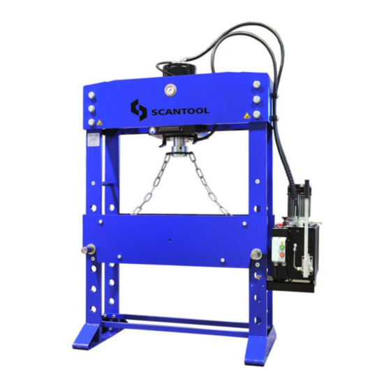
- Page 1 Industrivej 3-9 DK-9460 Brovst Tlf.: +45 98 23 60 88 Fax: +45 98 23 61 44 Manual SCANTOOL WSP Electro Hydraulic Workshop Press...
- Page 2 Tel.: +45 98 23 60 88 Fax.:+45 98 23 61 44 hereby declares that SCANTOOL Press WSP are manufactured in accordance with the provisions of the European Parliament and Council Directive 2006/42 / EC of 17 May 2006 And also in accordance with: •...
-
Page 3: Table Of Contents
Contents 1. GENERAL INFORMATION AND SPECIFICATIONS 1.1 T ECHNICAL DATA 2. SAFETY ADVICES ’ 2.1 U S RESPONSIBILITY 2.2 B ASIC SAFETY ADVICE 2.3 O UT OF USE 3. INSTALLATION 3.1 D ELIVER CONDITION 3.2 T RANSPORT 3.3 E NVIRONMENTAL CONDITIONS 3.4 F IXING OF MACHINE 3.5 I... - Page 4 Introduction his manual helps you to install, operate and maintain your press. Always read this manual before you start working with the machine. If you have questions, contact you supplier. The manual gives safety instruction where necessary to assure a safe machine. All instructions are clearly marked with the following symbol: Always follow the instruction mentioned with this symbol to prevent damages to the machine or injury to the operator.
-
Page 5: General Information And Specifications
1. GENERAL INFORMATION AND SPECIFICATIONS The Hydraulic Workshop Press is designed for: • Bending and straightening of beams, profiles, pivots, shaft etc. • (dis)assembly of bearings, bushings or pivots • stamping, punching, forming of wide range of materials Fig.1 Typical use of press This machine can be used in repair shops, work shops, etc. - Page 6 100T 100T- 160T 160T- 200T 1500 1500 2120 2120 2140 2140 2200 2270 2270 1000 1000 1350 1750 1410 1810 1610 1100 1500 1100 1500 1300 1315 1315 1665 2065 1725 2125 1925 Pressure force 1570 1570 1962 Max. pressure Cylinder Stroke Oil delivery ltr/min...
-
Page 7: Safety Advices
2. SAFETY ADVICE Note: the supplier of the press can not be held responsible for any damages or injuries in case the machine is modified or when maintenance is done by unqualified persons. 2.1 User’s responsibility Safe use of the hydraulic press can be achieved in daily work when all the necessary precautions are taken. -
Page 8: Out Of Use
Note: do not use the machine in the following conditions: • explosion hazard zones; • outdoors; • extreme temperatures +5°C < > +50°C Note: maximum pressing force can be exerted for a short time only. Do not use maximum force when the piston is extended further than ¾ of its length. -
Page 9: Installation
3. INSTALLATION Note: unpack the press and check if there are no visible transport damages. If so, do not further install the press. Place the machine in quarantine and contact your local supplier. 3.1 Deliver conditions The press is delivered in the following condition: •... -
Page 10: Environmental Conditions
ake sure the pallet truck is always placed in the middle of the machine. Make sure the forks of the pallet truck carries both lifting strips. Fig.6 Pallet truck transport Fork lift truck The press can be transported by a fork lift truck in case the forks of the fork lift truck can be set to the maximum inside width of the press. -
Page 11: Fixing Of Machine
3.4 Fixing of machine When the machine is positioned on the right working place, it should be fixed to 2x Ø10mm screws and plugs (not included). Preferable is a concrete floor to fix the press tight. In both feet there is a holes foreseen to fix the machine. -
Page 12: Oil Tank Filling
• Tighten all bolts with a torque of 50Nm • Fix the hydraulic hoses to the head of the press, using 2x hose clamps, cover, M8 bolt and ring. • Make sure there are no curves in the hoses between the clamps and connections of the hydraulic unit (see fig.11-right picture) Fig.10 Fixing hose clamps 3.6 Oil tank filling... -
Page 13: Electrical Connection
3.7 Electrical connection • The machine must be connected to a 5p 16A 400V/3~earthed socket *** • The electric circuit must be protected by a fuse of max. 16A • The electric connection socket must be equipped with a safety contact *** in case of a press with a different motor voltage, ask for the correct plug at your maintenance office Note: check if the turning direction of the motor is clockwise, looking... -
Page 14: Functions On The Press
4. FUNCTIONS ON THE PRESS 4.1 On/off switch The on/off switch is positioned on the front of the hydraulic tank. • Pushing the green button will start the motor of the hydraulic unit. There will be no movement of any parts after the motor runs. -
Page 15: Direction Control Valve
4.3 Direction control vise The direction control valve is located in the top cover of the hydraulic unit. The valve has 3 lever positions: • Middle position: if the lever has not been operated, the valve will always return to this position. There is no movement of the piston •... -
Page 16: Speed Setting Valve
Increasing pressure: • Start the hydraulic unit • Make sure the piston is in rest position (no force applied) • Turn the knob counter clockwise to loose pressure. Do not remove the knob! • Place your work piece on the table •... -
Page 17: Getting Started
5. GETTING STARTED To start the press for the first time, make sure: • The press is installed correct (see former paragraphs) • the oil tank is filled with sufficient oil • the hydraulic hoses are tightened to the cylinder and the hydraulic unit. 5.1 De-aerating the press When starting up for the first time, or when the hydraulic hoses have been disconnected of the hydraulic unit or cylinder, the system need to be de-aerated. -
Page 18: Positioning Of Cylinder
5.3 Positioning of cylinder All presses, except the 30T, are equipped with a movable cylinder which makes is possible to position the cylinder correct aligned with the work piece. To move the cylinder: • Un-tighten the 2 levers (or 4 levers in case of a 160T or 200T press), by turning it counter clockwise. - Page 19 Fig.18 Lifting chain bridge on piston head Fig.19 Lifting chain on table hook • Make sure the lifting hooks are position approximately in the middle of the axle. They are easy to move by hand • Move the piston of the cylinder upwards in “low speed” position of the speed setting valve.
-
Page 20: Regular Use
5.5 Regular use Place the work piece on the table so that it is aligned with the piston rod. If this is not possible, reposition the cylinder to achieve the best alignment Take care when performing operation on elements that are likely to fly off, break (especially casting element and hardened elements) or bounce up as a result of the applied force. -
Page 21: Servicing And Maintenance
6. SERVICING AND MAINTENANCE Note: replacing parts, electrical, mechanical or hydraulic, can only be done by qualified personal. Supplier can not be held responsible for damages or injuries as result of impropriate servicing. Daily Weekly 6-months 1-year Remove dust and Check oil level of Inspect all Replace the... -
Page 22: Guarantee
7. Guarantee If within 2 year of purchase this machine supplied by SCANTOOL A/S becomes defective due to faulty materials or workmanship we guarantee to repair or replace the machine or defective part or parts free of charge provided that: The product is returned complete to one of our Service Branches or Official Service Agents. - Page 23 Appendix I Electric scheme Fig. 21 Electrical scheme...
- Page 24 Appendix II Hydraulic scheme Fig. 22 Hydraulic scheme Description Oil tank Electrical motor 5&6 Tandem pump Pressure relief valve 3-way valve Check valve Check valve Hand pump Ball valve Pressure relief valve...
- Page 25 Appendix III Spare parts Parts list piston (all presses ) Pos Description 100T 160T 200T Piston shaft 030-506 060-506 100-506 160-506 200-506 36.2x3 NBR 46.2x3 NBR 62.2x3 NBR 110x3 NBR O-ring 96x3 NBR 90 Piston 030-505 060-505 100-505 160-505 200-505 Valve set valve tip 30-200-515...
- Page 26 Parts list cylinder (30T press only) Pos Description Complete cylinder assy 030-500 Piston head assy Piston head 030-507 Screw 30-200-M16x20 Wiper 55-63.6-5.3 Cylinder head 030-504 U-seal 55-65-7 O-ring 120x5 NBR 70 Complete piston assy 030-508...
- Page 27 Parts list cylinder (60T uptill 200T presses)
- Page 28 Pos Description 100T Complete cylinder assy 060-500 100-500 Cylinder mounting strip 060-601 100-601 Handle assy 60-100-520 60-100-520 Piston head assy Piston head 060-507 100-507 Screw 30-200-M16x20 30-200-M16x20 Wiper 75-83.6-5.3 90-102.2-7.1 Cylinder head 060-504 100-504 O-ring 160x5 NBR 70 210x5 NBR 70 U-seal 75-85-7 90-105-9...
- Page 29 Parts list hydraulilc unit (all presses)
- Page 30 Pos Description Electric motor 30-60-1.5/400/~3 30-60-1.5/400/~3 Tandempump 30-60-1.0/3.15 30-60-1.0/3.15 Pressure relief 30-200-RV22-2A100 30-200-RV22-2A100 Directional control valve 30-200-RM40-0010G 30-200-RM40-0010G Check valve 30-200-KO3/8-0.5 30-200-KO3/8-0.5 Check valve 30-200-CV10-2BN 30-200-CV10-2BN Handpump 30-200-MP25-300 30-200-MP25-300 Speed setting valve 30-200-RS2/38 30-200-RS2/38 Pressure regulator 30-200-RV22-2A300MT 30-200-RV22-2A300MT Knob pressure regulator 30-200-KNOB-RV22 30-200-KNOB-RV22 Handle speed setting valve...
- Page 31 Parts list press (all presses) Pos Description 100T Hydraulic hose set 30-60-627 30-60-627 100-160-627 Lifting chain assy 030-617 060-617 100-617 Complete hydraulic unit 30-6-1.5kW 30-6-1.5kW 100-2.2kW Electric cable assy 30-200-5x1.5mm2 30-200-5x1.5mm2 30-200-5x1.5mm2 Cable Plug 30-200-CEE 16A 5p 30-200-CEE 16A 5p 30-200-CEE 16A 5p On-off switch 30-200-Elmark...
- Page 32 Pos Description 100T Table axle assy Axle 30-60-303 30-60-303 100-303 Screw 30-60-M16x30 30-60-M16x30 100-200-M16x50 Ring 30-200-A17 30-200-A17 30-200-A17 Lifting hook 30-60-602 30-60-602 100-160-602 Label warning 30-200-227276 30-200-227276 30-200-227276 Pressure gauge assy Gauge 30-200-213.53-63 30-200-213.53-63 30-200-213.53-63 Screw 30-200-M3x8 30-200-M3x8 30-200-M3x8 Pos Description 100T D=1500 160T 160T D=1500...
- Page 33 Pos Description 200T Hydraulic hose set 200-627 Lifting chain assy 200-617 Complete hydraulic unit 160-200-3kW Electric cable assy 30-200-5x1.5mm2 Cable Plug 30-200-CEE 16A 5p On-off switch 30-200-Elmark Emergency switch 30-200-EL1-B174 Frame strip assy Strip 200-201 Screw 100-200-M16x50 Ring 30-200-A17 Shaft 200-304 Clip ring 200-55x3.2...
Need help?
Do you have a question about the WSP 30T and is the answer not in the manual?
Questions and answers