
Related Manuals for Clarke CBMEW1


Summary of Contents for Clarke CBMEW1
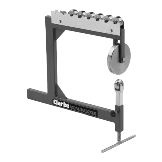
- Page 1 BENCH MOUNTED ENGLISH WHEEL MODEL NO: CBMEW1 PART NO: 7627901 OPERATION INSTRUCTIONS ORIGINAL INSTRUCTIONS DL0321 ISS1...
- Page 2 INTRODUCTION Thank you for purchasing this CLARKE English Wheel. The CBMEW1 is suitable for forming and shaping light gauge steel and aluminium panels and for removing dents, smoothing hammer marks, flattening welds etc. Pressure is applied by adjusting the lower anvil roller.
-
Page 3: Safety Precautions
WARNING: THE USER MUST FOLLOW ALL INSTRUCTIONS WITHIN THIS INSTRUCTION BOOKLET To protect against serious injury, use common sense and observe the following precautions when using this product. CLARKE International is not responsible for misuse of the equipment. • ALWAYS study these instructions before operating and pay close attention to all warnings. - Page 4 INVENTORY NO DESCRIPTION NO DESCRIPTION Frame Hex Nuts ”-20 Upper Wheel: 146mm Hex Bolts ”-20 x 1 ” Lower Wheel Adjustment Screw 10 Lower Wheel Axle Rods 11 Upper Wheel Clevis Pin Lower Wheels: ”,1”,1 ”, ”, 5”, 9” and Flat Lower Wheel Bracket 12 Locking Knob Bracket Spacer Rod...
-
Page 5: Specification
SPECIFICATION Model CBMEW1 Dimensions Length (mm) Width (mm) Height (mm) Throat (mm) Frame Thickness (mm) Weight (kg) 12.15 Capacity Mild Steel 16 Gauge, 1.5mm Aluminium 14 Gauge, 1.8mm Copper 14 Gauge, 1.8mm WORKBENCH MOUNTING • The forces exerted on the English Wheel during operation are substantial. - Page 6 ASSEMBLY 1. Insert the bracket spacer rod into the bottom of the lower wheel bracket, as shown. 2. Turn the frame upside down and insert the lower wheel bracket into the frame, as shown. • Inserting the wheel bracket into the frame when it is upside down will keep the spacer rod inside the bracket.
- Page 7 5. Position the upper wheel between the frame arms. Insert the upper wheel clevis pin through the arms and wheel and secure with the hairpin cotter pin. NOTE: If the cotter pin does not easily slide into the clevis pin hole, insert it as far as you can and use a small hammer to tap it the rest of the way.
-
Page 8: Before Starting Work
BEFORE STARTING WORK WARNING: METAL EDGES CAN BE VERY SHARP. AVOID INJURIES BY WEARING APPROVED SAFETY GLOVES. Check that all component parts are secure and that the rollers turn freely. Practice on some scrap metal before attempting work on the actual stock work- piece. -
Page 9: Operation
Check that all moving parts move smoothly and freely. After use, keep the rollers clean and occasionally lubricate moving parts with a light oil. This will also inhibit any corrosion of the metal components. For any technical problems contact you CLARKE International Service Department on 020-8988-7400. -
Page 10: Exploded Diagram
EXPLODED DIAGRAM PARTS LIST Frame 11 Hex Bolt 1/4”-20 x 1 1/4” Lower Wheel Adjustment 12 Lower Wheel 1/2” Radius Screw Bracket Spacer Rod 13 Lower Wheel 1” Radius Lower Wheel Bracket 14 Lower Wheel 1 1/2” Radius Lower Wheel Axle Rod 15 Lower Wheel 2 1/2”... -
Page 11: Associated Products
ASSOCIATED PRODUCTS Bench Vice - CL CV3RB 3 in 1 Sheet Metal Sheet Metal Folder - Machine - SBR610 CMF24B •75mm Jaw Width •Bends, Slip Rolls & •Max Sheet Steel Shears Sheet Capacity:22 swg •75mm Jaw Opening Metal:1mm (0.71mm) •46mm Jaw Depth •Minimum Rolling Dia.: •Max.
Need help?
Do you have a question about the CBMEW1 and is the answer not in the manual?
Questions and answers