Table of Contents
Advertisement
Quick Links
Advertisement
Table of Contents

Related Manuals for Knightsbridge OS001 Series


Summary of Contents for Knightsbridge OS001 Series
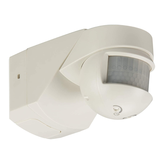
- Page 1 INSTALLATION & MAINTENANCE MANUAL OS001 series 230 V 50Hz...
- Page 2 OS001 / OS001B SAFETY GENERAL INSTRUCTIONS These instructions should be read carefully and retained after installation by the end user for • Installation of this product should only be carried ou future reference and maintenance. latest Building and current IEE Wiring Regulations (B These instructions should be used to aid installation of the following products: OS001 / OS001B •...
- Page 3 Using the base as a tem • Using the base as a template, secure the base to th • infringe with any gas/w infringe with any gas/water pipes or electrical cabl • Using the base as a template, secure the base to the desired surface using the fixings supplied ensuring not to infringe with any gas/water pipes or electrical cables (see Fig 2) Fig 1 e base as a template, secure the base to the desired surface using the fixings supplied ensuring not to...
- Page 4 • Switch on power supply and check for correct operation INTERNAL OR EXTERNAL CORNER MOUNTING Internal or external corner mounting: INTERNAL OR EXTERNAL CORNER MOUNTING Note: sensor can be corner-mounted by removing part of the base as shown (breakable areas) This sensor can be corner-mounted by removing part of the bas •...
- Page 5 BLANKING INSERTS • Blanking inserts are supplied that can be cut and attached to the lens to blank out areas of interference as required i.e. heat sources, public pathways etc. TEST MODE TEST MODE For initial setup of the sensor, turn the time control fully anti-clo For initial setup of the sensor, turn the time control fully anti-clockwise to the minimum position clockwise to the maximum position and the lux control fully clockwise to the maximum position...
- Page 6 l setup and walk test have been completed, adjust the time and lux set SENSOR SETUP aking adjustments to the PIR settings ensure the sensor is powered do Note: When making adjustments to the PIR settings ensure the sensor is powered down 3 seconds –...
- Page 7 GENERAL The product should be recycled in the correct manner when it reaches the end of its life. Check local authorities for where facilities exist. Clean with a soft dry cloth only, do not use other materials or solutions which may damage the product WARRANTY This product has a warranty of 1 year from date of purchase.
- Page 8 ML Accessories Limited LU5 5TA AKJUN18_V2 www.mlaccessories.co.uk...
Need help?
Do you have a question about the OS001 Series and is the answer not in the manual?
Questions and answers