Advertisement
Table of Contents
Advertisement
Table of Contents

Related Manuals for Knightsbridge OS0010


Summary of Contents for Knightsbridge OS0010
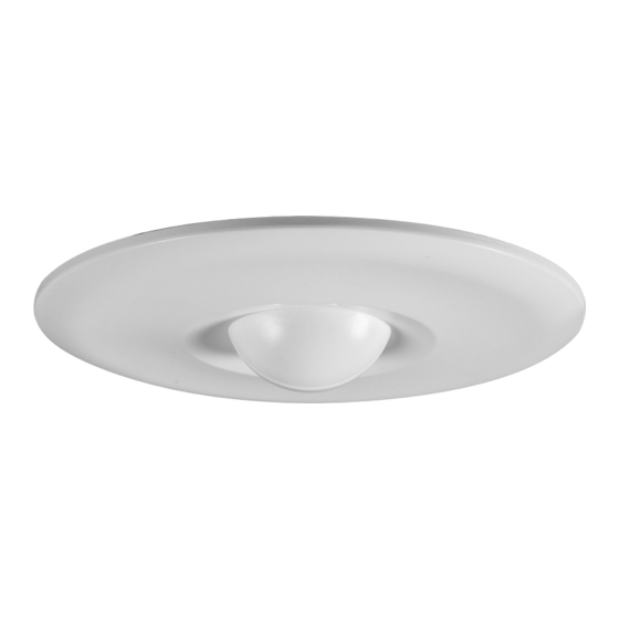
- Page 1 INSTALLATION & MAINTENANCE MANUAL OS0010 230V 50Hz Ø...
-
Page 2: General Instructions
These instructions should be read carefully and retained after installation by the end user for future reference and maintenance. These instructions should be used to aid installation of the following product: OS0010 SAFETY • Installation of this sensor should only be carried out by a qualified electrician or competent person... -
Page 3: Distance Setting
Connect the sensor to the luminaire and mains supply (via terminal connector) ensuring the correct polarity is • observed. See Fig 2 for the wiring diagram (Live (brown), Neutral (blue) and Switched Live (L’)) Fig 2 • Switch on power supply and check for correct operation. L’ L’ L L N Switch on power supply and check for correct operation. • Fig 2 Fig 2 • Switch on power supply and check for correct operation. DIP SWITCH LAYOUT Live (brown) • Switch on power supply and check for correct operation. Neutral (blue) DIP SWITCH LAYOUT Fig 2 On DIP SWITCH LAYOUT Fig 2 • Switch on power supply and check for correct operation. Load/ Position I luminaire On DIP SWITCH LAYOUT DIP SWITCH LAYOUT On Position 0 Position I... -
Page 4: Warranty
DETECTION DIAGRAM DETECTION DIAGRAM Ceiling Mounting height 1.8m-2.5m Floor 2m to 10m WARNING WARNING This product must be disconnected from the circuit if subjected to any high voltage or insulation resistance testing. This product must be disconnected from the circuit if subjected to any high voltage or insulation Irreparable damage will occur if this instruction is not followed. resistance testing. Irreparable damage will occur if this instruction is not followed. GENERAL The unit should be recycled in the correct manner when it reaches the end of its life. Check local authorities for where GENERAL... - Page 5 ML Accessories Limited LU5 5TA SBOCT16_V2 www.mlaccessories.co.uk...
Need help?
Do you have a question about the OS0010 and is the answer not in the manual?
Questions and answers