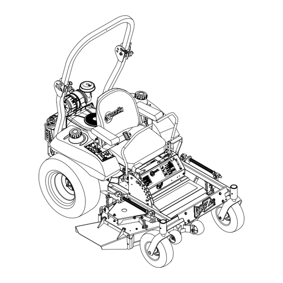
Exmark LAZER Z HP Setup Instructions
Hide thumbs
Also See for LAZER Z HP:
- Operator's manual (60 pages) ,
- Operator and parts manual (32 pages) ,
- Parts manual (21 pages)
Advertisement
Quick Links
Loose Parts
Note: Use the chart below to verify that all parts have been shipped.
Part #
Description
323-6
Cap Screw, Hex 3/8-16 x 1
98-5975
Washer, Belleville
3290-357
Nut, Hex Flange 3/8-16
103-1309
Warranty Registration Form
109-0936
Literature Pack (Kawasaki)
109-0034
Literature Pack (Kohler)
103-2106
Keys
106-7022
Tube, Oil Drain
109-0036
Manual, Operator's
109-0035
Manual, Parts
103-9143
DVD, Exmark Safety Video
1-809066
Tie, Plastic (5/16" x 24")
1-850285
Manual, Engine Operator's
106-8294
Manual, Engine Operator's
32128-20
Nut, 5/16-18 Whizlock
Installing the Rollover Protection
System (Roll Bar)
1. Remove sides and top of crate from the base.
2. Remove roll bar components from the crate.
3. Remove roll bar tubes from sides of crate.
4. Remove the two brackets used to mount the
bottom of the upper roll bar tube to the crate.
5. Remove the 1/2-13 x 3 1/4 capscrews and 1/2-13
hex flange lock nuts from the two brackets at
each end of the upper roll bar tube and retain for
later use (Fig. 1).
Figure 1
SETUP INSTRUCTIONS
Qty
Use
8
8
Installing the Rollover Protection System (Roll Bar)
8
1
Fill out and return to Exmark
1
Contains unit specific material
1
Unit ignition
1
Kawasaki only; Draining engine oil
1
1
Read and view before operating machine
1
1
Kohler only; To secure Engine Oil Drain Hose to Roll Bar
1
For units with Kohler engines only
1
For units with Kawasaki engines only
4
To fasten seat tracks to unit seat frame
6. Remove the (4) 1/4" lag screws holding the
wheel hub brackets to the crate bottom and
discard.
7. Raise the rear of the unit approximately 10-12"
and support it with jack stands or equivalent
support.
POTENTIAL HAZARD
♦ Raising the rear of the unit for assembly relying
solely on mechanical or hydraulic jacks could
be dangerous.
WHAT CAN HAPPEN
♦ The mechanical or hydraulic jacks may not be
enough support or may malfunction allowing
the unit to fall, which could cause injury.
HOW TO AVOID THE HAZARD
♦ DO NOT rely solely on mechanical or hydraulic
jacks for support. Use adequate jack stands or
equivalent support.
8. Locate the left and right lower roll bar tubes.
9. Align lower roll bar tubes along rear engine frame
(Fig. 2).
LAZER Z
For Serial Nos. 600,000 and Higher
CAUTION
Page 1 of 4
109-2027 Rev. A
®
HP
Advertisement

Subscribe to Our Youtube Channel
Related Manuals for Exmark LAZER Z HP


Summary of Contents for Exmark LAZER Z HP
- Page 1 Cap Screw, Hex 3/8-16 x 1 98-5975 Washer, Belleville Installing the Rollover Protection System (Roll Bar) 3290-357 Nut, Hex Flange 3/8-16 103-1309 Warranty Registration Form Fill out and return to Exmark 109-0936 Literature Pack (Kawasaki) Contains unit specific material 109-0034 Literature Pack (Kohler) 103-2106 Keys...
- Page 2 10. LOOSELY install lower roll bar hardware (four 3/8- 15. Locate the upper u-shaped section of the roll 16 x 1 capscrews, four spring disk washers and bar. Install the upper roll bar section using the four 3/8-16 whizlock nuts) to the tubes on each two 1/2-13 x 3 1/4 capscrews and two 1/2-13 side.
- Page 3 DANGER CAUTION POTENTIAL HAZARD POTENTIAL HAZARD ♦ Charging the battery may produce explosive ♦ If the ignition is in the “ON” position there is gasses potential for sparks and engagement of components. WHAT CAN HAPPEN ♦ Battery gasses can explode causing serious WHAT CAN HAPPEN ♦...
- Page 4 Installing the Motion Control Levers 1. Loosen and remove the two (2) 3/8” x 1” bolts and spring disc washers which attach the motion control levers to the control arm shafts for shipping and the two (2) 3/8” x 1” bolts and spring disc washers which are screwed into the control arm shafts.
Need help?
Do you have a question about the LAZER Z HP and is the answer not in the manual?
Questions and answers